Harnessing the sun’s vast energy through photovoltaic technology is a sustainable solution for modern power needs, ranging from small off-grid setups to large-scale grid-connected arrays. Understanding the synergy between solar panels, charge controllers, batteries, and inverters is vital for building a system that is both efficient and reliable. By mastering the principles of series and parallel wiring, selecting appropriate cable gauges to minimize voltage drop, and implementing rigorous safety measures—such as DC isolators and grounding—users can ensure a high-performance installation. This guide explores the technical framework of solar structures, providing the essential knowledge required to design, protect, and maintain a functional solar power system.
Prefer listening? You can play the audio version of the rest of this article below.
Reviewing the Solar System Structure and Solar Electrical Wiring Diagram
The sun is a massive energy source that will remain usable for the next 5 billion years. About 6,000 million years have passed since the birth of this fiery sphere, and the fossil fuels stored deep underground, wind energy, flowing water, ocean waves, and other forms of energy are among the results of the amount of energy the Earth receives from the sun. One way to use solar energy is a solar power system. In these systems, a phenomenon called the photovoltaic effect generates electricity. Certain materials in these solar panels, when exposed to light, cause an electric current to flow in their circuit. In this article, we examine the steps for installing and wiring a solar power system. But before that, let us introduce the components of a solar power system.
The structure of solar or photovoltaic systems can generally be divided into three main sections:
| Description | Section |
|---|---|
| This section converts the sun’s radiant energy into electrical energy (without a mechanical intermediary). It should be noted that the output current and voltage of these panels are DC. | Solar Panels |
| This section controls all system characteristics and, based on the completed design and the consumer’s needs, injects the input power of the panels into the load or the battery. In this section, the specifications and components vary depending on the electrical load and consumer needs, as well as weather conditions. | Control Section |
| Given the DC output of photovoltaic panels, the load can be DC or AC. Also, with different photovoltaic panel arrangements, the needs of different consumers can be supplied with different power levels. | Consumer or Electrical Load |
For a comprehensive understanding of electrical wiring systems, we highly recommend reviewing this article.
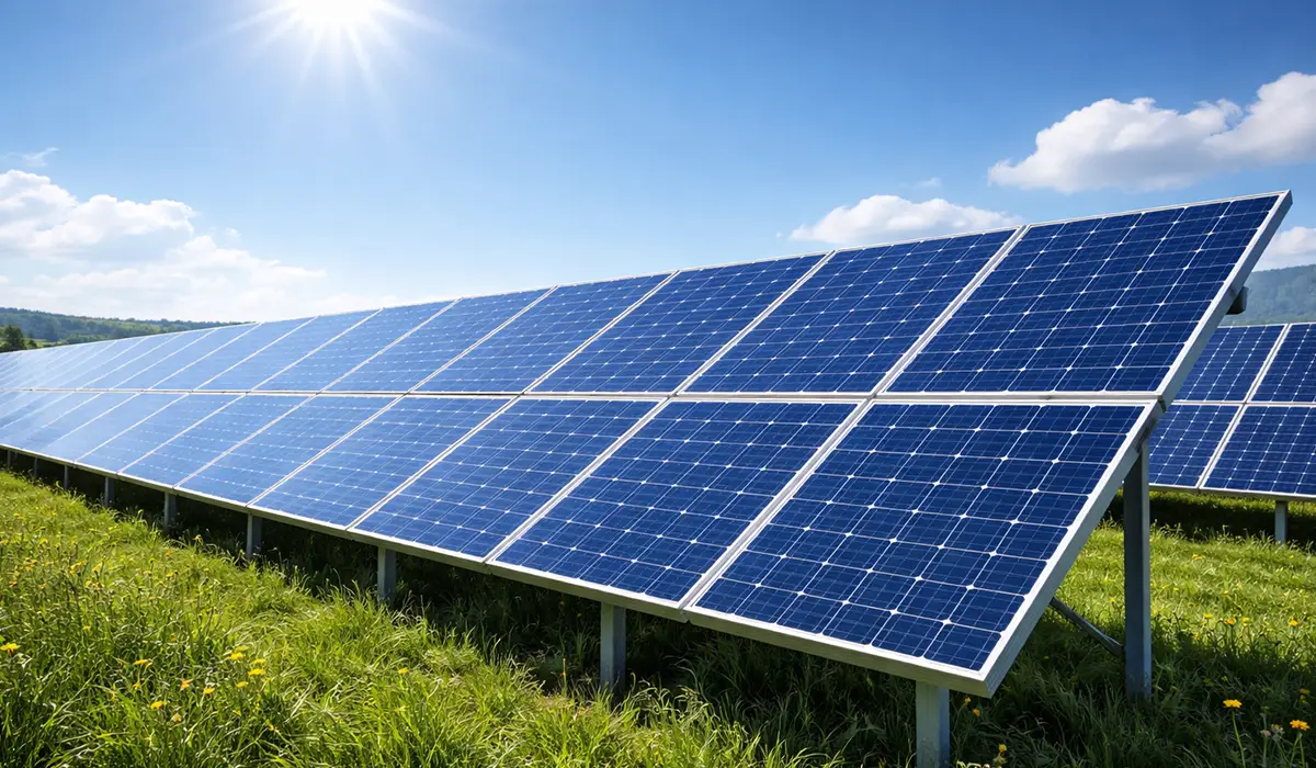
Solar Panel
Naturally, the main and most important components of a solar power system are its panel or panels. Panels are manufactured in various types. In the structure of a solar system, panels obtain their required energy from the sun, so the greater the solar energy, the higher the received power will be. Panels also generate electricity in the absence of direct sunlight, meaning in shade, but the amount is very small and limited.
The output voltage of most panels under load is around 14 to 18 volts, which is the level at which a single solar panel can charge a 12-volt battery. If you connect the leads of a voltmeter to the output terminals of a solar panel that is not connected to any load, you may see up to about 26 volts. This voltage in an unloaded panel, in so-called open circuit conditions, is normal and predictable, but when the output is connected to a load, the voltage drops to around 14 to 18 volts.
For wiring a solar power system, if you have more than one panel and your decision is to use a 12-volt solar power system, you must connect the panels in parallel so that while keeping the output voltage constant, you increase the total system power.
But if you intend to use higher voltages, you need more than one panel, and to obtain higher voltages you must connect them in series to reach the desired voltage. For example, if your goal is a 24-volt supply, you must connect two 12-volt panels in series, and if you want a 48-volt system, you must connect four 12-volt panels in series.
If the information related to solar panels was interesting and informative to you, researching solar grounding systems can be very engaging.
Solar Panel Battery
Another component of a solar power system is solar batteries, which are mostly used in off-grid solar system structures or grid-tied solar system structures with battery backup. Except for grid-connected systems where the solar array is connected directly to an inverter, solar panels are rarely used to directly power loads.
The reason is that the received power of solar panels changes in proportion to the intensity of sunlight. In that case, with the available power fluctuating up and down, the resulting electricity will not be usable for many sensitive loads.
The structure of a grid-connected solar system is designed so that the inverter manages this fluctuation in production power and adapts to it; and if load demand increases, the shortfall is supplied through grid power. In off-grid systems or grid-connected-with-backup types, batteries store the produced energy and provide it to consumers in a stable and uniform manner.
The energy produced by panels is usually stored in deep-cycle lead-acid batteries. These batteries are very similar to 12-volt car batteries, but due to differences in their internal construction, they can undergo several hundred significant charge and discharge cycles.
Although the voltage of most of these batteries is 12 volts, they are also produced in 6-volt versions. To achieve higher power levels, these batteries can be connected in series or parallel, like solar panels. Here too, a series connection increases the voltage and the total power of the battery set, and a parallel connection keeps the voltage constant while increasing the received current and therefore increasing power.
This article serves as a valuable resource for those seeking detailed information on energy storage capacity.
Solar Controllers
Except for the grid-connected solar system structure, in other cases and designs, solar power systems need a controller that supervises the current delivered to the battery or drawn from it. If a battery or batteries face excessive and unnecessary charging, they will be damaged and quickly fail. A similar condition occurs when a system lacks a controller and the batteries are fully depleted or discharged. The solution to this problem is a device called a controller.
Of course, in some conditions, especially for small solar power systems, the need for a controller may not be strongly felt. An example is the design and installation of a small solar panel placed in part of a vehicle, for example on the dashboard under the windshield or on the rear shelf between the rear speakers, suitable for vehicles that are usually left unused for a significant time and whose battery loses its proper performance and efficiency.
The reality is that the output power of such panels is not high enough that, after the battery is fully charged and current continues, they could damage the internal plates of the battery or evaporate the acid water.
Although such applications are rare, in most cases every solar power system needs controllers to supervise and manage battery charging and discharging and to keep the battery in proper condition.
Solar controllers are responsible for protecting batteries and safeguarding them against excess charge sent from the solar module. These devices also have another function: if loads connected to the batteries attempt to draw extra and unreasonable energy and expose the batteries to deep discharge and serious damage, the controller disconnects the connection between them.
Many controllers are equipped with a small LCD screen that displays essential system information such as battery charging current and also the power produced by the solar module.
If the purchased model lacks such a screen, it is better to have a standard digital multimeter or a clamp meter so that you can occasionally check different parts of the circuit and ensure correct operation.
Further exploration of measuring electrical parameters can be found in the following recommended reading.
Factors Affecting the Selection of Solar Controllers
Selecting solar controllers depends on the following four factors:
| Notes | Selection Factor |
|---|---|
| Must match the nominal voltage of the solar system (e.g., 12 V, 24 V, 48 V) | System Voltage |
| Controller rating must be equal to or greater than the solar module’s maximum output current | Solar Module Output Current (A) |
| Controller must handle the peak current drawn by all connected loads | Maximum Load Current (A) |
| More detailed LCD displays allow monitoring of production, consumption, and battery amp-hours | LCD Display Detail Level |
Some solar power system installers add a fifth factor to the four above: battery type. This mainly applies to older solar controllers that worked only with a specific battery type.
Modern controllers work with various lead-acid batteries without any special problem, although even in these models, during initial settings, the battery information used must be defined.
All controllers, even the cheapest models, display essential system information on their LCD screen. Produced and stored power compared with power currently being consumed, and the available battery amp-hours, are among this information. Some more advanced and better-equipped types also provide comparative information about daily production and consumption.
If the details you gathered about controller selection were interesting and insightful, you may find diving deeper into capacitor bank behavior equally captivating.
Solar Inverter
Another component of a solar power system is the inverter. The electricity produced by the panel in a solar power system has a low voltage and is DC (direct current), while household electricity has a high voltage and is AC (alternating current). To operate and power building electrical equipment that runs on AC power, you will need a device called an inverter, which in addition to changing the voltage and raising it to mains voltage, also changes its nature from DC to AC.
When purchasing inverters, you must consider three things:
| Notes | Consideration |
|---|---|
| Applies to off-grid systems; must match the nominal battery bank voltage | Battery Set Output Voltage |
| Inverter power rating must equal or exceed the total connected load power | Allowable Power Rating |
| Pure sine wave is preferred for sensitive loads; modified sine wave may not suit all devices | Output Waveform Quality |
If the content related to solar inverters was both interesting and helpful, further study of three-phase power cables could be just as fascinating.
Solar Panel Loads
If loads require mains voltage, they must be connected to the inverter, but if they operate at low DC voltages, they must be connected to the controller.
Installation of a Grid-Connected Solar Panel System
In designing and wiring a grid-connected solar power system, compared to off-grid systems or grid-connected-with-backup systems, there are minor differences as follows:
In grid-connected systems, there is no battery and no solar controller. In that case, the output of the solar panels is connected to the input of a grid-tie inverter, and its output is connected to the building’s internal wiring.
Usually, to obtain higher DC voltages, several solar panels are connected in series. For example, in the diagram below, sixteen solar panels are connected in series, creating a nominal voltage of 192 volts and, consequently, a peak voltage of 400 volts.
For a comprehensive understanding of IEC 61439 design verification, we highly recommend reviewing this article.
Installation of a grid-connected solar panel system
- Due to the high DC voltage present in these systems, additional protective measures are mandatory. For example, the solar module must be connected to the earthing (grounding) system. Between the solar module and the inverter, you must use a DC switch (also called an isolator switch), and you must use an RCD or GFI so that in case of a short circuit, the connection between the solar module and the rest of the system is immediately disconnected.
- In the above diagram, several DC switches are used between different modules so that by turning them off, the connection between different sections can be separated and the produced voltage of each set can be reduced. With the installation of these switches, repair and maintenance become simpler and safer, and in emergencies the risk of electric shock or fire is reduced.
- In this system, you will need two AC isolator switches: one between the inverter and the distribution board that can fully connect or disconnect solar power from the home’s internal wiring, and another switch that can isolate the internal wiring from grid power.
- If you install this type of solar power system, you must contact your regional electricity company so they can replace the existing meter with a bidirectional model or any other acceptable and suitable meter.
- Before installing different solar equipment, ensure that the purchased models for a grid-connected system comply with local standards and are approved by the relevant organizations. Also, if your goal is to sell electricity to the national grid, before final installation ensure that the completed work is accepted and approved by the regional electricity company at the installation location.
Further exploration of solar panel can be found in the following recommended reading.
Features of Installing and Wiring a Grid-Connected Solar Power System
In terms of solar panels, controller, and batteries, the design of a grid-connected-with-backup system has many similarities to off-grid systems, and the only difference is in the arrangement after the battery.
The most important advantage of these systems is that they can be used in three ways: use the produced electricity to supply the entire building’s electrical needs, feed their output into specific circuits in the building, or use it to supply only one specific circuit.
If you are looking for more information about Wiring a Grid-Connected Solar Power System, it is recommended not to miss reading this article.
Protection of the Solar System Circuit
In all introduced systems, circuit protection plays a very important role so that the user can be confident that if a short circuit occurs in part of the system, the relevant circuits will be safely disconnected. Observing this condition is mandatory in all low-voltage and high-voltage systems.
The most important problem that low-voltage systems, such as those operating with a 12-volt battery, face is the high circuit current. In that case, the passage of a 100-ampere current, even for a very short time, can easily create a significant electrical shock that can lead to death or injury.
If the circuit is not properly protected, as soon as a short circuit occurs, the wiring quickly heats up and catches fire and within a few seconds melts. These conditions can easily cause burns to the user or create a fire, so the remedy must come before the event: by applying necessary protective measures, arrangements must be made so that in the event of a short circuit, the entire system does not face heavy damage and losses.
If the insights you gained from solar circuit protection were intriguing, exploring arc flash protection requirements might be of great interest to you as well.

Grounding the Solar System
In wiring any type of solar power system, the negative terminal or pole of the battery must be properly connected to earth or the grounding line. If an appropriate grounding line has not been provided at the site, a ground rod must be installed near the solar power system installation location and used.
Having a ground fault protection system reassures the user that if there is a fault in the solar module, the flow of current will stop and the risk of damage to the controller or solar module is eliminated.
Although most inverters and solar controllers are equipped with this system, further investigation into the definite presence of it does no harm.
For all solar panels with power above 100 watts and all systems installed in buildings, if the inverter or controller used lacks a ground fault protection system, using a separate residual current device (RCD) is necessary and mandatory.
Many professional and cautious installers believe that even with a factory-installed ground fault protection system inside the controller or inverter, installing and using a separate ground fault protection system is not a bad idea, so that if one fails to operate, the other activates and preserves the safety and health of the related systems.
Make this recommendation the guiding principle of your work and act on it, because purchasing an RCD or GFI is not expensive, but the consequences of using them are very valuable.
If the information about grounding the solar system was valuable and interesting to you, researching types of earthing systems could be just as captivating.
Protection of the DC Circuit in a Solar Power System
In very small systems with power below 100 watts, the fuse installed in the controller alone can protect the circuit. In larger systems designed to power some devices that operate on DC power and where there is no controller anywhere in the circuit, you must use a suitable fuse on the line connected to the positive pole of the battery. The fuse location in the circuit must be where all current drawn from the battery passes through it.
In DC systems that include several separate circuits, it is better to equip each one with an independent fuse. If you use a 12- or 24-volt system, you can also use the same switches and fuses used in the building’s internal wiring connected to the grid. However, in DC systems with higher voltages, the use of special DC current fuses is mandatory.
Since the negative line connected to the negative pole of the battery is grounded near the battery, when connecting different devices to DC circuits, there is no need to use a separate earth/ground line for each device.
For protecting DC circuits, it is better to use a DC isolator switch between the solar module and the inverter or controller. Using another separate switch between the battery and the controller or inverter also provides greater reassurance. If the purchased controller or inverter lacks an internal RCD or GFI system, it is better to obtain a separate RCD or GFI and place it between the solar module and the inverter or controller.
One of the most important advantages of using multiple switches and fuses at different critical points in the circuit is that if a problem occurs in one part of the system, the fuse near the problematic circuit repeatedly trips or blows, which helps identify the fault location. In such cases, if you first turn off the nearby switch and then replace the fuse, by turning the switch back on, the fuse will trip again, and from the switch side you may hear a spark sound and possibly smell burning, which is due to a fault or problem in adjacent circuits. If troubleshooting is done in the dark, by repeating this action and watching the problematic area, you may even see the spark glow from the defective point, which can greatly help identify the faulty component.
If the material related to DC circuit protection was both useful and intriguing to you, diving into IP and NEMA protection ratings will likely be equally fascinating.
Protection of the AC Circuit in a Solar Power System
The required power for AC circuits must be supplied from the main distribution board. The distribution board must use an earthing system and, in addition to an RCD or GFI, must also be equipped with a ground leakage current breaker system. Here too, in the same way you grounded DC circuits, use a separate grounding line and connect AC circuits to it.
In addition to all of this, using an AC isolator (disconnect) switch between the inverter and the distribution board is necessary. This is a suitable safety and protective measure, although observing it in grid-connected systems is considered a mandatory requirement.
DC isolator switches have only two terminals and are usually installed in the positive line, and by disconnecting one of the lines, they make the system fully safe. In AC circuits, which have a high voltage (110 or 220 volts) and include phase and neutral lines, if an installation error occurs and the switch disconnects only the neutral line, then the phase line is not disconnected and in some severe conditions, such as the user being barefoot, high humidity, wet ground, etc., the risk of electric shock is not fully eliminated. For this reason, AC isolator switches are designed with four terminals (two input terminals and two output terminals) so that when activated, both phase and neutral lines are simultaneously and completely disconnected.
The building’s internal wiring is like standard and normal wiring, but for installing and commissioning sections that operate at mains voltage, you must use a skilled and qualified electrician.
If you enjoyed learning about AC circuit protection, investigating switchboard protection standards might also offer a similarly engaging and informative experience.
Cable Selection in a Solar Power System
After the solar power system wiring diagram is determined, it is better to specify the cable lengths for different parts of the diagram and determine the appropriate cable diameter for each part.
Regarding the installation and operation of solar power systems, three different cable groups must be considered:
| Key Requirement | Cable Group |
|---|---|
| Must be UV-resistant, moisture-resistant, and dust-resistant; obtainable from solar equipment suppliers | Cables Connected to the Solar Array |
| Must carry both charging current from the module and discharge current to loads; thickest available types recommended | Cables Connected to the Battery or Batteries |
| Must match the maximum anticipated current; thicker cables required in low-voltage DC circuits due to high current | Cables Leading to the Loads |
In all cases, ensure that you use a cable capable of carrying the maximum current anticipated in the system.
If at this stage you consider future expansion, later when you want to expand your system and increase its power, you will not face any problems because you have already used thicker cables with higher amperage capacity.
If the content on cable selection was interesting and insightful to you, continuing to explore overvoltage protection categories could be both exciting and beneficial.
Determining Cable Diameter
Incorrect selection of cable diameter is one of the biggest mistakes users commonly make when designing solar power systems.
As you know, significant power in low-voltage systems is wasted along the cables. This is because in these systems, the current in the circuit is very high, and power losses, which are proportional to the square of the current, will also be high.
In other words, with increasing current, the cable or wire resistance also increases, and to overcome this resistance, we are forced to use thicker cables.
When transferring lower voltages (for example from the solar module to the controller, and also supplying DC power to low-voltage devices) using weaker cables, you must ensure that the cable diameter matches the existing conditions.
If the selected cable is too weak, a noticeable voltage drop will occur and may disrupt normal system operation.
Under no circumstances use weaker cables, because then you will face higher voltage drops and normal operation of some devices and loads may be disrupted.
Further exploration of Current density can be found in the following recommended reading.
Determining Cable Length
If your goal is to supply multiple loads at significant distances from each other, instead of taking all of their power from a single line, to reduce the length of each branch cable it is better to use multiple parallel paths. This has two advantages: first, the total length of each cable is reduced, and second, the load is divided and distributed among multiple circuits. With this method, the required diameter of each cable is reduced, which makes installation and shaping easier.
If you want to implement this wiring method in a building, to create each of the separate circuits mentioned, you must use a distribution board.
In that case, with a little more time and accepting a small extra cost, if at the beginning of each separate circuit in the main board you place a miniature circuit breaker and below it indicate the circuit specification (for example upper-floor lighting, lower-floor outlets, etc.), when one of the circuits has a problem, first, the electricity for all parts will not be cut off, and second, as soon as you open the board door, you can identify the tripped fuse and therefore identify the faulty circuit.
Selecting Solar Module Cable
For this section, you must use cables resistant to ultraviolet sunlight, moisture from snow and rain, and the destructive effects of dust and similar pollution. You can obtain such cables from the same stores that sell solar power system parts and accessories.
Controller Cable
When calculating the cable cross-section needed to connect the controller and batteries, you must consider the current flowing from the solar module to the batteries as well as the current drawn from them. Usually, the maximum current used to charge the batteries is much higher than the current drawn from them.
If the information related to topic Controller Cable was interesting and informative to you, researching Three-Phase Power Cable Selection can be very engaging.
Battery Connection Cables in a Solar Panel System
These cables and the required battery terminals can be obtained from battery makers (automotive electricians) and the same stores that sell batteries. Due to the high current in these cables, it is recommended to choose the thickest available types.
Load Wiring
If the final goal is to use an inverter and power loads with AC electricity equivalent to the grid, wiring is carried out in a standard manner similar to normal building wiring.
If the goal is to use 12 or 24 volts DC, the wiring method does not differ from the method mentioned earlier, except that this time, due to the high circuit current, thicker cables or wires must be used.
In a residential building, you usually face different circuits, each with a specific duty: one circuit for lower-floor lighting, one for upper-floor lighting, and depending on needs, one or two circuits for supplying power to different appliances and electrical devices.
As you know, in low-voltage systems, a large amount of the available power is wasted inside cables. This is because power loss is proportional to the square of the current, and with increasing current, power losses increase exponentially and more sharply. Therefore, cable lengths should be reduced as much as possible, especially those carrying higher currents.
Solar Panel Wiring
Simple solar panel wiring Electric boat circuit with solar panel charging An off-grid 12-volt solar system in which an inverter is used to supply the building’s required AC power
Next Step
After completing the wiring diagram, it is time to add the following to your shopping list: cables, battery terminals, fuses, on/off switches (or isolators), a ground rod or ground rods, and a distribution board. Adding more details to the wiring diagram, such as specifying outlet locations and the lengths of different cables, helps complete the diagram.
Fuses and Isolator Switches
One of the most important things that must not be overlooked when designing and installing solar power systems is providing measures for electrically isolating different parts from each other. This becomes important during system installation and also during repair and maintenance. Do not forget that working on systems that use relatively low voltages is also dangerous.
Even small and compact systems must use a suitable fuse between the battery and the controller or inverter. In that case, if the system faces a problem or a fault occurs, the blowing or tripping of an inexpensive fuse is far better than the burning of a controller or the failure and possibly explosion of one or more batteries.
In some cases, you may encounter inverters or controllers that have an internal factory switch; in that case, buying and installing an additional switch is considered unnecessary expense. Usually, that switch simultaneously disconnects or connects the path of both AC and DC currents at the inverter output.
In addition to the mentioned fuse, all different systems, even small ones, must be equipped with isolator switches. In this way, during repair and maintenance, the connection between the battery set and the rest of the system can easily be disconnected.
Also, when installing systems with more than one solar panel and for all grid-connected systems, you must use an isolator switch and provide the ability to disconnect the solar module from the rest of the system. The presence of this isolator switch is very sensitive and vital for solar modules of 100 watts and higher.
If the distance between the solar panel installation location and the inverter or controller is significant, installing two isolator switches, one near the inverter or controller and the other near the solar panels, is not a bad idea. In that case, in emergencies or even during repair and maintenance, disconnecting the solar panels from the rest of the system is easily possible.
When purchasing and installing a DC isolator switch, ensure that it can carry high DC currents and that its contacts under load operate in a way that, when switching such high currents on or off, they do not spark. Remember that these isolator switches can also be obtained from the same stores that supply solar power system equipment and accessories.
If the system is grid-connected, you will also need AC isolator switches so that by manually activating them you can disconnect or connect the inverter’s connection to the local power grid. In that case, it is better to place one of these AC isolator switches after the inverter and the second near the electrical distribution board.
Since switchgear plays a crucial role in the protection of electrical panels, obtaining more information about switchgear safety standards can be very important and essential.
Plugs and Sockets
In 12- or 24-volt systems and for currents up to 30 amperes, you can use the same standard and ordinary switches and outlets.
However, you should not use ordinary plugs and sockets for connecting low-voltage devices to low-voltage circuits, because there is the risk that you might accidentally connect the plug of a low-voltage device to a high-voltage outlet and then watch that device fail and burn.
Instead of using standard plugs and sockets, it is better to use special 12-volt system types used in recreational boats and caravans, or at least use plugs and sockets that differ from those used for AC mains electricity.
Since in DC circuits, the negative cable is always connected to the circuit ground/earth, creating a separate earth wire for these low-voltage sockets is not necessary.
Conclusion
A solar power system is built around three main parts: solar panels (DC output), a control section (managing power flow to the load or batteries), and the electrical loads (DC or AC). Proper wiring depends on choosing series or parallel panel and battery connections to achieve the required voltage, and on using controllers, inverters, grounding, and protective devices like fuses, isolator switches, and RCD/GFI where needed. Careful cable sizing and minimizing cable length are essential, especially in low-voltage, high-current circuits, to reduce voltage drop and improve safety. Use this structure to finalize your wiring diagram, complete the protection plan, and prepare a correct purchase list before installation.