
Underground electrical conduit is one of the most important tools we have to avoid this kind of headache. When we choose the right conduit type, correct burial depth, and good trench preparation, the system normally runs quietly in the background for 20–40 years. If we choose badly, the same system can become a constant source of trouble and cost. In this guide I try to explain, in simple engineer-to-engineer language, how to design and install underground conduit in a way that is practical, code-compliant, and friendly for future maintenance.
We will look at common underground electrical conduit types (like PVC, RMC/IMC, EMT, HDPE duct, and fiberglass), discuss typical National Electrical Code (NEC) burial depths, compare PVC Schedule 40 vs Schedule 80, and talk about when EMT direct burial makes sense after the 2023 NEC update. I will also explain the difference between direct burial cable and conduit systems, and share some real-world best practices that I learned from projects in residential, commercial, and utility environments.
Prefer listening? You can play the audio version of the rest of this article below.
What Is Underground Electrical Conduit?
Underground electrical conduit is basically a protective pipe that we bury under the ground to carry electrical conductors. Instead of putting the cable directly into the soil, we first install this hollow raceway and then pull the wires inside. The conduit creates a barrier between the cable insulation and the soil, stones, moisture, and future excavation work.
When we design an underground conduit system, we usually want to achieve four main goals at the same time:
- Mechanical protection – prevent rocks, compacted soil, vehicle wheels, and digging tools from damaging the cable jacket.
- Moisture and corrosion control – separate the conductor insulation and metallic parts from constantly wet or contaminated soil.
- Organization and future access – keep different circuits organized, and make it possible to add or replace cables later without digging again.
- Code compliance – meet NEC 300.5 cover requirements and any local rules, or international standards such as BS 7671 or CSA C22.2.
Compared with a cable that is buried directly in the soil, a well-designed conduit system acts like a long-term shell. For critical feeders, data centers, campus networks, solar plants or industrial facilities, this shell is a kind of insurance: if technology changes or the load increases, you can pull new cables in the same conduit or in spare ducts, instead of breaking the pavement and digging everything again.
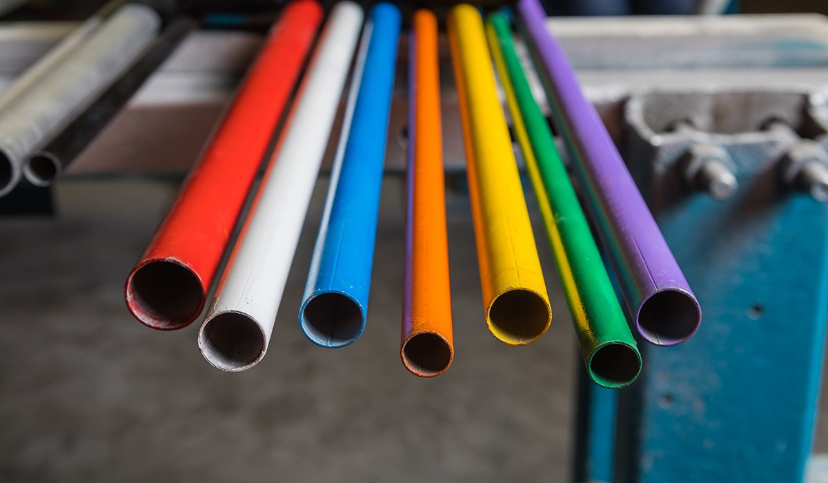
In practice, underground electrical conduit is made from different materials. Each material has its strong points and its weak points, so we must match it with the project conditions.
- PVC (Schedule 40 / Schedule 80) – rigid, non‑metallic, corrosion‑resistant, and very common for residential and light‑commercial work.
- RMC / IMC – rigid metal conduit for maximum mechanical protection and good electromagnetic shielding.
- EMT – thin‑wall steel tubing, mostly for above‑ground work, sometimes allowed for direct burial with special conditions in 2023 NEC.
- LFMC / LFNC – liquid‑tight flexible conduits, often used for short connections to outdoor equipment.
- HDPE duct – flexible polyethylene duct in long coils, very popular in utility and telecom projects, especially with HDD.
- Fiberglass (RTRC) – reinforced thermosetting resin conduit with very good corrosion and temperature resistance.
The design and installation of busbar systems inside power switchboards play a crucial role in ensuring efficient electrical distribution. For a deeper understanding, check out the article that discusses its components and benefits.
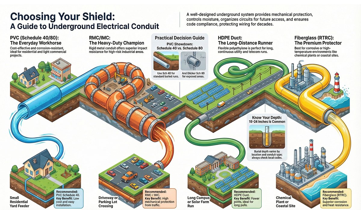
Common Underground Conduit Types (Pros, Cons and Where They Fit)
When choosing underground conduit, I normally think in a very simple way: how strong does it need to be, how long will it stay in the ground, how corrosive is the soil, and how much budget do we have? Below is a practical summary for each main type, based on what I see on site.
Busbar fabrication machines have evolved to improve precision and efficiency in the manufacturing process. This article highlights three key types, providing insights into modern fabrication techniques.
PVC (Polyvinyl Chloride) – Schedule 40 / Schedule 80
PVC is the everyday workhorse for many underground electrical jobs. It is non‑metallic, electrically non‑conductive, and corrosion‑resistant in most normal soil. It is light, cheap, and easy to cut and glue, which makes it attractive for residential and light commercial work.
Typical advantages of PVC underground conduit include:
- Lightweight and easy to handle, even in tight trenches.
- Fast installation with solvent cement joints.
- Corrosion‑proof in most non‑aggressive soil conditions.
- Low material cost and good availability at most suppliers.
Key limitations you should remember:
- Lower mechanical strength compared with rigid metal conduit.
- Can become brittle in very low temperatures if not rated and handled correctly.
- Softens at high temperature, so above‑ground exposed sections must be checked for derating and UV protection.
In practice, PVC is used for feeders to detached garages, small commercial laterals, parking lot lighting, and many other light‑to‑medium duty installations where the soil is not highly aggressive and heavy traffic is limited.
RMC (Rigid Metal Conduit) and IMC (Intermediate Metal Conduit)
Rigid metal conduit is the heavy‑duty champion when it comes to underground mechanical protection. Both RMC and IMC have strong walls that resist crushing and impact much better than PVC, and they also provide excellent shielding against electromagnetic interference.
Main advantages of RMC/IMC underground include:
- Superior crush and impact resistance for high‑risk areas.
- Good EMI shielding when sensitive circuits are nearby.
- Often preferred by inspectors where conduits pass under driveways or loading docks.
But we also pay a price for this strength:
- Higher material cost compared with PVC.
- Heavier weight and slower installation time.
- Need for cutting, reaming, and threading tools, and careful corrosion protection at damaged coating areas.
For exposed risers coming out of the ground, or for industrial yards with forklifts and trucks moving all day, RMC or IMC is usually my first choice.
EMT (Electrical Metallic Tubing)
EMT is the thin‑wall steel conduit that many electricians love for indoor work because it is light and easy to bend. Traditionally, it was not used directly in the ground because it corrodes much faster than rigid steel, especially in wet soil.
The 2023 NEC brought an important change: Article 358.10 now allows EMT to be used for direct burial and in concrete if the tubing and all the fittings are specifically listed and identified for that purpose. This gives some new options, but in my personal practice I still use EMT very carefully underground.
If we have a very controlled environment, good drainage, and concrete encasement, EMT might be acceptable. For long‑term duct banks in normal soil, I still prefer PVC, HDPE, RMC/IMC, or fiberglass because they give more predictable life in the ground.
LFMC / LFNC (Liquid‑Tight Flexible Conduits)
Liquid‑tight flexible metal (LFMC) or non‑metallic (LFNC) conduits are not intended for long underground runs, but they are very useful as short connectors at the ends of the system. For example, where a buried PVC or RMC raceway connects to an outdoor pump, AC condenser, or control panel, we often use a short flexible piece to handle vibration and small movement.
Advantages of these flexible conduits include:
- Easy routing around equipment and small obstacles.
- Good vibration resistance.
- Strong liquid‑tight performance when we use the right fittings.
However, they are more expensive per metre, and friction builds quickly for long pulls. So I keep them short, just where flexibility is really needed.
HDPE (High‑Density Polyethylene) Duct
HDPE duct is common in utility and telecom projects where we need long continuous runs. It usually comes in long coils and has a very smooth inner surface, which makes cable pulling easier and reduces the number of joints.
Typical uses for HDPE underground duct are:
- Solar and wind farm collector systems.
- Campus medium‑voltage and low‑voltage distribution.
- Telecom and data fibre routes.
- Road and river crossings with horizontal directional drilling (HDD).
HDPE needs fusion welding or mechanical couplers and some special tools, so it is more common in larger projects handled by specialised contractors than in small residential jobs.
Fiberglass (RTRC – Reinforced Thermosetting Resin Conduit)
Fiberglass, or RTRC, is like the premium non‑metallic option. It does not rust, it is lighter than steel, and it keeps its strength at higher temperatures better than PVC. Because of this, it is attractive in aggressive soil or industrial areas.
You will often see RTRC used in:
- Chemical plants and refineries.
- Coastal areas with salty groundwater.
- Large duct banks where engineers expect long service life with little corrosion risk.
PVC Schedule 40 vs Schedule 80 (Which One Should We Use?)
When a younger colleague asks me about PVC underground, usually the first question is: “Should we put Schedule 40 or Schedule 80?” The answer depends mainly on mechanical risk and code requirements. Both can be used for underground electrical conduit where they are listed and permitted, but their wall thickness and strength are different.
Schedule 40 PVC
Schedule 40 is the standard wall thickness and is very common in residential and light commercial work. If the conduit is buried at proper depth, in normal soil, and not exposed to heavy vehicle load, Schedule 40 is usually sufficient.
I normally choose Schedule 40 when:
- The trench is in a garden or yard without heavy truck traffic.
- The conduit will stay buried and not be exposed above ground where it can be hit.
- The project is cost‑sensitive but still needs a clean and safe installation.
Schedule 80 PVC
Schedule 80 has a thicker wall, so it gives better impact resistance and higher mechanical strength. It is heavier and slightly more expensive, but in some locations it is clearly the safer choice.
I recommend or use Schedule 80 when:
- The conduit comes out of the ground and is exposed at the side of a building or pedestal.
- The run passes under a driveway, parking area, or place with repeated vehicle load.
- The specification or the local authority explicitly asks for Schedule 80 in exposed or high‑risk areas.
A common and economical design is to use Schedule 40 for the buried horizontal run and Schedule 80 or RMC only for the vertical risers and exposed sections. In this way we keep the cost under control but still protect the weak points.

EMT Underground After the 2023 NEC Update
The 2023 edition of the NEC made many electricians raise their eyebrows. Article 358.10 now allows EMT to be used for direct burial and in concrete, but only when the tubing and fittings are listed and identified for that purpose. In theory, this means we can design EMT underground systems that are code‑compliant.
In reality, most soil is a very aggressive environment for thin‑wall steel. If the coating gets damaged during handling or installation, corrosion can start quickly. Because of this, many experienced contractors still avoid long EMT runs directly in the soil and prefer PVC, HDPE, RMC/IMC, or RTRC for serious underground work.
My personal rule is simple: if an EMT underground section is short, well‑protected, and the local inspector agrees, it may be acceptable. For anything long or critical, I choose a more robust conduit material.
When HDPE or Fiberglass (RTRC) Is the Better Choice
We do not always need HDPE or RTRC, but in some projects they clearly give a better long‑term result than standard PVC.
Typical situations where I consider upgrading are:
- Very long pulls where the number of joints should be minimised.
- Road or river crossings done with horizontal directional drilling (HDD).
- Industrial or coastal areas with aggressive soil and high temperature.
- Duct banks for MV or LV feeders that are designed for several decades of service with future capacity built in.
HDPE shines in long continuous runs and HDD crossings. RTRC shines in places where corrosion and temperature are serious concerns. Using them in the right place can save a lot of trouble 10 or 20 years later.
For more information on this, you can visit the article Underground Cable Installations.
NEC Burial Depths and Clearances (How Deep Should Conduit Go?)
One of the most common questions from homeowners and even some junior electricians is: “How deep do I need to bury this conduit?” The NEC answers this in Table 300.5 by giving minimum cover values for different wiring methods and locations. Cover means the distance from the top of the conduit or cable to the finished ground level.
Typical values you will see in many residential and light‑commercial situations are:
- Direct burial UF/USE cable in a yard – around 24 inches (about 600 mm) of cover.
- Non‑metallic conduit such as PVC or HDPE – often 18 inches (about 450 mm) when not in concrete.
- Rigid metal conduit – sometimes as low as 6 inches (about 150 mm) because the wall is very strong.
- Under streets, commercial driveways or parking lots – typically 24 inches or more for extra protection.
- Under a 2–4 inch concrete slab – the NEC may allow reduced burial depth because the slab itself acts like a protective plate.
For most small feeders in a residential yard, I normally see conduits at 18–24 inches depth. In commercial and industrial projects with higher voltage, 24–36 inches or even more may be required. Always check Table 300.5 and, very important, talk to the local authority having jurisdiction (AHJ) because local rules may be stricter than the NEC minimum.
Underground power rarely travels alone. Water, gas, and telecom services also need space in the same trench. Good practice is to keep at least 12 inches (300 mm) of vertical separation when crossing other utilities and to use sleeves or concrete encasement when electrical lines cross gas mains or other critical services.
Example Chart – Typical Underground Burial Depths
Figure: Example NEC‑style minimum cover depths for common underground wiring methods.
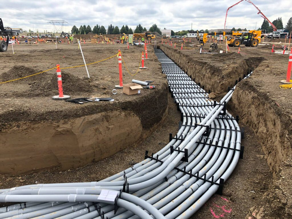
Trenching, Bedding, and Warning Tape (Small Details, Big Result)
Even if we select the correct conduit type and burial depth, a poor trench can still destroy the installation. I normally think about three separate steps: excavation, bedding/backfill, and marking.
Excavation and trench method
For very short runs you can dig by hand, but for longer distance a trencher or excavator is faster. Near existing utilities, hydro‑vac or vacuum excavation is much safer because it lets us expose pipes and cables without hitting them with a bucket tooth.
The bottom of the trench should be reasonably flat and free of big stones or debris. A sharp stone under the conduit can later press into the wall when the soil is compacted, creating a weak point.
Bedding and backfill
I like to place a layer of fine sand or granular material under the conduit and then again above it. Many specifications require 4–6 inches (100–150 mm) of fine material below and above the raceway. This helps to distribute load and protect the conduit from point impact.
We should avoid using broken concrete, bricks, or large stones as backfill around the conduit. Frozen soil blocks that later thaw and settle can also create voids and pull on the risers. Compaction in layers helps to control settlement and keep the finished grade stable.
Warning tape and location records
As a final step, I always recommend bright coloured warning tape about 12 inches above the conduit or direct buried cable. This tape is a simple but very effective warning for future excavations. Some tapes contain a metallic strip so that cable locators can find them easily.
Together with warning tape, accurate as‑built drawings and GPS coordinates (when possible) make life much easier for the next team who will work on that site.
Conductor and Conduit Sizing for Underground Runs
Once the mechanical part of the design is clear, we must think about the conductors inside the conduit. Underground locations are always considered wet, so wire insulation must be suitable for wet conditions and ampacity calculations must respect NEC rules.
Choosing wire type
For most building feeders in North America, the usual answer is THWN or THWN‑2 copper or aluminium conductors. They are rated for wet locations and are widely available. For special high‑voltage or utility projects, other cable types may be used, but THWN‑2 in PVC or HDPE conduit is a very common combination.
Conduit fill, ampacity, and voltage drop
The NEC limits how much conductor cross‑section area can be placed in one raceway. If we exceed this limit, pulling becomes hard and the conductors can overheat during operation. For more than two conductors, the maximum fill is usually 40% of the internal conduit area.
When several current‑carrying conductors share the same conduit, ampacity must be derated. For long feeders, we also check voltage drop and sometimes we choose a larger wire size even if ampacity is technically enough.
Planning pulls and junction boxes
From a practical point of view, pull points are just as important as calculations. I try to keep the total bend angle between pull points to 360 degrees or less and use long‑radius sweeps instead of tight 90‑degree elbows. This reduces pulling tension and protects the cable jacket.
Simple Conduit Sizing Example – 200 A Residential Feeder
As a quick example, imagine a 200 amp single‑phase residential feeder from a meter pedestal to a main panel in the house.
- We select the conductor size (for example 3/0 AWG copper or 4/0 AWG aluminium THWN‑2, depending on local code and temperature ratings).
- We calculate conduit fill and choose a raceway size that keeps the fill under 40% including phase, neutral, and equipment grounding conductors.
- We check voltage drop and, if the distance is long, we consider upsizing the conductors or conduit.
- We think about the future: will the owner later want an EV charger, workshop, or extra building? If yes, we may install a slightly larger conduit or add one spare conduit now.
Exactly the same logic applies to commercial feeders and campus duct banks. The only difference is scale: more conductors, more parallel conduits, and usually more spare capacity built into the design.
Quick Selection Table – Underground Conduit by Project Type
| Project type | Recommended conduit | Reason for this choice |
| Small residential yard feeder | PVC Schedule 40 | Low cost, easy to install, enough protection at correct depth. |
| Exposed riser at building corner | PVC Schedule 80 or RMC | Extra impact resistance where mowers or vehicles may hit. |
| Driveway or parking lot crossing | RMC / IMC or concrete‑encased PVC | High mechanical protection under repeated vehicle load. |
| Long campus or solar farm run | HDPE duct | Long continuous pulls, fewer joints, good for HDD crossings. |
| Chemical plant or coastal site | Fiberglass (RTRC) or PVC‑coated steel | High corrosion resistance and long expected service life. |
Installation Best Practices – From Layout to Final Pull
Good underground conduit systems do not happen by accident. They are the result of careful planning and disciplined execution. Here are some simple habits that help a lot in the field:
- Mark the route clearly before digging and check for existing services.
- Avoid unnecessary bends and keep enough straight length before and after each sweep.
- Use proper primer and solvent cement for PVC joints, and listed fittings for metal conduit.
- Pull in a rope or jet line first to confirm the path is open before pulling heavy cables.
- Use suitable cable lubricant and control pulling tension to stay inside manufacturer limits.
- Seal all entries to buildings and boxes to keep water, insects, and rodents out.
The fabrication of busbars often faces various challenges, including overcoming common challenges in the production process. Learn about strategies to handle these obstacles effectively in the article.
Direct Burial vs Conduit – Which One Should You Choose?
Sometimes running UF or USE cable directly in the soil is allowed and gives the lowest first cost. In other cases, a full conduit system is clearly the smarter decision. The right choice depends on run length, risk level, and how much flexibility we want in the future.
Direct burial (UF/USE cable)
Main advantages:
- Lowest material cost and fewer installation steps.
- Fast for simple, short runs in low‑risk areas.
Main disadvantages:
- Limited mechanical protection – cable jacket and soil must do all the work.
- Any future repair or upgrade requires new excavation.
- Not very flexible if the owner later wants more circuits or higher load.
Conduit systems (PVC, HDPE, RMC, RTRC)
Main advantages:
- Higher mechanical protection and more control over routing.
- Possibility to pull new cables later without digging again.
- Option to include spare ducts for future circuits or data cables.
Main disadvantages:
- Higher initial cost for materials and labour.
- More design work to select conduit size, type, and installation details.
For very short and simple residential runs, direct burial may be acceptable. For anything strategic – workshops, commercial buildings, campuses, EV charging, or solar plants – I personally recommend investing in a proper underground electrical conduit system. Over the life of the installation, the extra flexibility usually pays back many times.
Standards, Compliance, and Documentation
Underground electrical work is strongly regulated because failures can be expensive and dangerous. In North America, the main reference is the National Electrical Code (NEC). For underground raceways we especially look at:
- NEC 300.5 – minimum cover requirements for direct burial cable and conduit.
- NEC 352 – rules for rigid PVC conduit.
- NEC 358 – rules for EMT, including the 2023 update for direct burial where listed.
Other countries use different documents, such as BS 7671 in the UK or CSA standards in Canada. But the philosophy is similar: protect the cables mechanically, choose safe burial depths, and document everything clearly.
After the installation is complete, it is important to produce as‑built drawings showing the route, depth, size, and type of each underground conduit. If you can add coordinates or reference measurements from fixed points on the site, future maintenance will be much easier and safer.
Safety and compliance are paramount in busbar manufacturing. This article covers essential safety measures and regulatory requirements to maintain standards in the industry.
FAQs – Underground Electrical Conduit


