
Capacitor banks are essential components in modern power distribution systems, playing a crucial role in improving grid efficiency and power quality. By compensating reactive power, these systems correct power factor and significantly reduce energy losses across industrial and commercial facilities. However, one critical phenomenon poses a major challenge during capacitor bank operation: inrush current. This sudden, high-magnitude current surge that occurs at the moment of switching can damage expensive equipment, trigger protective device malfunctions, and disrupt overall grid stability. Understanding capacitor bank inrush current is not just an academic exercise—it’s a practical necessity for electrical engineers, facility managers, and anyone responsible for power system reliability.
In this comprehensive technical guide, we examine capacitor banks and their applications across various industries, define inrush current and explain the physics behind this phenomenon, analyze the critical factors that determine inrush current magnitude, explore the equipment damage and operational problems caused by uncontrolled switching, and present proven methods for calculating, measuring, and mitigating inrush current effects. We also discuss compliance with relevant electrical standards and safety requirements that govern capacitor bank installations.
Prefer listening? You can play the audio version of the rest of this article below.
Understanding Capacitor Banks in Power Systems
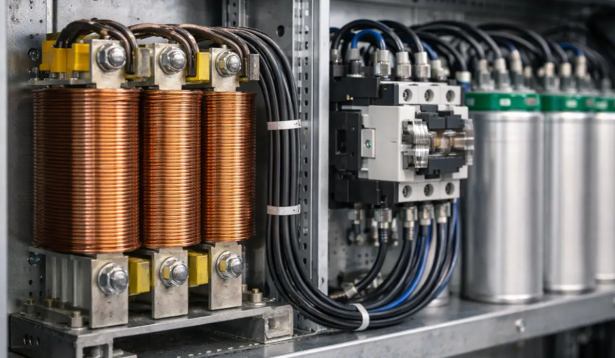
A capacitor bank is an assembly of multiple capacitor units connected in series or parallel configurations to achieve desired reactive power compensation in electrical networks. These systems function as crucial power quality improvement devices by providing leading reactive power to offset the lagging reactive power consumed by inductive loads such as motors, transformers, and fluorescent lighting ballasts. The fundamental principle involves storing electrical energy in electrostatic fields and releasing it back to the system, thereby reducing the reactive power burden on generators and transmission infrastructure.
If you are looking for more information about Electric power system, it is recommended not to miss reading this article.
Types of Capacitor Bank Configurations
Capacitor banks are implemented in three primary configurations, each suited to specific operational requirements:
Fixed capacitor banks remain permanently connected to the electrical system and provide constant reactive power compensation. These installations are cost-effective and simple, making them ideal for facilities with stable, predictable reactive power demands. A typical application is a manufacturing plant with continuous motor loads operating at relatively constant power factors throughout production shifts.
Manually-switched capacitor banks allow operators to adjust reactive power compensation by connecting or disconnecting capacitor stages based on observed power factor or reactive power measurements. This configuration offers flexibility for facilities with varying load profiles but requires active operator intervention. For example, a commercial building might switch capacitor stages manually during peak occupancy hours to maintain optimal power factor and avoid utility penalties.
Automatically-switched capacitor banks employ power factor controllers or reactive power relays to monitor system conditions continuously and switch capacitor stages on or off as needed. These sophisticated systems maintain target power factor automatically without operator intervention, making them suitable for facilities with highly variable loads. A data center with fluctuating IT equipment loads represents an ideal application for automatic capacitor banks, as the system adjusts compensation in real-time to maintain power factor above 0.95 lagging.
Industrial Applications and Benefits
Capacitor banks deliver measurable economic and technical benefits across diverse applications. In industrial facilities, improved power factor reduces demand charges on electricity bills—utility companies typically penalize customers with power factors below 0.90 or 0.95, and capacitor banks eliminate these penalties by maintaining compliance. A 500 kW manufacturing facility operating at 0.75 power factor draws approximately 667 kVA from the utility; installing capacitor banks to improve power factor to 0.95 reduces apparent power demand to 526 kVA, cutting demand charges proportionally.
Transmission and distribution systems benefit from reduced I²R losses as lower current flows through conductors and transformers for the same real power delivery. Voltage profiles improve throughout the network as reactive power support from distributed capacitor banks counteracts voltage drop. Line and transformer capacity increases become available without physical infrastructure upgrades, as reduced reactive power flow frees capacity for additional real power transmission.
However, these advantages come with engineering challenges. Improper capacitor bank design, inadequate protection systems, or failure to account for inrush current phenomena can negate benefits and introduce new problems. This reality makes understanding inrush current essential for any power system professional involved in capacitor bank specification, installation, or maintenance.
Defining Capacitor Bank Inrush Current
Inrush current, also known as switching current or energization transient, is the sudden, high-magnitude current surge that flows into a capacitor bank at the instant of connection to an energized electrical system. This phenomenon occurs because an uncharged or discharged capacitor initially presents near-zero impedance to the source voltage—effectively behaving as a short circuit during the first microseconds after switch closure. The capacitor must charge from zero volts to system voltage almost instantaneously, and this rapid change in voltage (dV/dt) produces an extremely high current spike governed by the fundamental capacitor equation: i = C(dV/dt).
Comparison with Rated Current
The distinction between rated current and inrush current is critical for proper equipment selection and system protection. Rated current represents the steady-state RMS current that flows through a capacitor bank during normal continuous operation after energization transients have decayed. This current is determined by the capacitive reactance at system frequency: I_rated = V / X_C = V × 2πfC, where V is system voltage, f is frequency (50 or 60 Hz), and C is total capacitance.
For a practical example, consider a 50 kVAR capacitor bank connected to a 400V, 50 Hz three-phase system. The rated current per phase is approximately 72 A. However, the inrush current for this same bank can reach 720 to 1,440 A (10 to 20 times rated current) depending on system impedance, switching instant, and other factors. This represents a current magnitude 10 to 20 times higher than the steady-state operating current, and this surge occurs within the first few milliseconds after switch closure.
| Current Comparison Parameters | VALUES |
|---|---|
| Typical rated current (50 kVAR, 400V system) | 72 A |
| Peak inrush current (10× multiplier) | 720 A |
| Peak inrush current (20× multiplier) | 1,440 A |
| Inrush current duration | 1-5 milliseconds |
| Inrush frequency | 200-2,000 Hz |
| Decay time constant | 0.5-2 milliseconds |
| Typical source impedance influence | 0.05-0.5 Ω |
| Voltage at peak inrush (worst case) | Peak system voltage |
Inrush Current Waveform Characteristics
The inrush current waveform exhibits distinctive characteristics that differentiate it from other transient phenomena in power systems. At switch closure, the current rises almost instantaneously to a sharp peak value determined by system voltage at that instant, total circuit impedance, and capacitor bank capacitance. Following this initial peak, the current oscillates at a high frequency (typically 200 to 2,000 Hz, well above fundamental power frequency) superimposed on the normal 50 or 60 Hz component. This high-frequency oscillation results from the LC circuit formed by system inductance and capacitor bank capacitance, with damping provided by circuit resistance.
The oscillation amplitude decays exponentially with a time constant determined by circuit resistance and inductance: τ = L/R. In typical power systems with relatively low resistance, the decay time constant ranges from 0.5 to 2 milliseconds, meaning the high-frequency transient diminishes within 5 to 10 milliseconds after switch closure. After this transient period, only the steady-state rated current at power frequency remains.
Critical Factors Affecting Inrush Current Magnitude
Multiple system parameters and operating conditions influence the severity of capacitor bank inrush current. Understanding these factors enables engineers to predict inrush current levels and implement appropriate mitigation strategies during system design in compliance with standards for switchgear and busbar systems.
Capacitance Value
Total capacitance directly affects inrush current magnitude through the relationship i = C(dV/dt). Larger capacitor banks with higher microfarad ratings draw proportionally higher inrush currents because more charge must flow to establish the voltage across increased capacitance. For example, doubling capacitor bank size from 50 kVAR to 100 kVAR approximately doubles the inrush current peak, assuming other system parameters remain constant. This linear relationship makes capacitance the most straightforward factor to assess when estimating inrush current levels.
For a comprehensive understanding of Capacitance, we highly recommend reviewing this article.
Source Impedance and Short-Circuit Capacity
System source impedance, comprising resistance and inductive reactance between the power source and capacitor bank connection point, fundamentally limits inrush current magnitude. Lower source impedance—characteristic of “stiff” power systems with high short-circuit capacity—permits higher inrush currents because less impedance restricts current flow during the charging transient. A typical 400V industrial panel fed from a 1,000 kVA transformer might exhibit source impedance of 0.1 Ω, resulting in higher inrush currents compared to a remote capacitor bank connected through 50 meters of cable adding another 0.3 Ω of impedance.
The relationship between source impedance and peak inrush current follows Ohm’s law during the initial charging instant: I_peak = V_peak / Z_source, where V_peak is the instantaneous system voltage at switch closure and Z_source is total series impedance. Systems with infinite short-circuit capacity (zero source impedance) would theoretically produce infinite inrush current; in practice, even very stiff systems have some resistance that limits current to finite values, though these values can still reach dangerously high levels.
Pollution degree and overvoltage category concepts
Understanding pollution degree and overvoltage category is essential for ensuring the proper insulation and safety of electrical systems. These classifications define the environmental conditions and
Switching Instant Relative to Voltage Waveform
The point on the voltage sine wave at which switch closure occurs dramatically influences inrush current magnitude—this factor often produces the widest variation in observed inrush current for the same capacitor bank. If switching occurs when system voltage crosses zero (voltage zero-crossing), the capacitor must charge from zero to peak voltage (±√2 × RMS voltage) within one quarter-cycle. However, if switching occurs at voltage peak (for example, +565V in a 400V line-to-line system), maximum instantaneous voltage applies across the uncharged capacitor, driving maximum current through system impedance.
Real-world example: A 75 kVAR capacitor bank switched at voltage zero-crossing might produce 850 A peak inrush current, while the same bank switched at voltage peak could generate 1,600 A—nearly double the magnitude. This voltage-dependent behavior explains why uncontrolled mechanical contactors, which close at random points on the voltage waveform, produce highly variable inrush current magnitudes from one switching event to the next.
Back-to-Back Capacitor Bank Configuration
When multiple capacitor banks connect to the same bus or adjacent buses in a power system, already-energized banks can discharge into newly-connected banks during switching, creating a parallel current path that bypasses system source impedance. This “back-to-back” switching scenario produces the most severe inrush current conditions because the effective impedance between capacitor banks is often much lower than source impedance—perhaps only the resistance and inductance of short bus conductors connecting the banks.
Consider a substation with two 100 kVAR capacitor banks connected to the same 11 kV bus. When the first bank energizes, it charges through system source impedance and experiences typical inrush current. When the second bank switches on while the first remains connected, the first bank partially discharges into the second through the low-impedance bus connection. Peak inrush current in back-to-back switching can reach 50 to 100 times rated current—far exceeding the 10 to 20 times multiplier seen in single-bank energization. This extreme current stresses not only the newly-closing switch but also the already-energized bank, potentially causing internal fuse operation or capacitor element failure.
Residual Voltage on Capacitor Bank
After a capacitor bank disconnects from the system, voltage across the capacitor elements does not instantly decay to zero. Instead, residual voltage remains, slowly discharging through internal resistors (if installed) or leakage resistance. If the bank re-energizes while retaining residual voltage, the effective voltage difference driving inrush current depends on the algebraic sum of system voltage and residual voltage at the switching instant.
For example, if a capacitor bank retains +300V residual voltage and reconnects when system voltage is +400V (same polarity), only 100V voltage difference drives the initial charging current, resulting in reduced inrush. However, if the bank retains +300V and reconnects at -400V system voltage (opposite polarity), the 700V voltage difference produces significantly higher inrush current than normal. Most standards require discharge resistors to reduce capacitor voltage to less than 50V within 5 minutes after disconnection, minimizing this re-energization concern.
| Factors Affecting Inrush Current | IMPACT |
|---|---|
| Larger capacitance (increased kVAR rating) | Increases inrush |
| Lower source impedance (stiff system) | Increases inrush |
| Switching at voltage peak | Maximum inrush |
| Switching at voltage zero-crossing | Minimum inrush |
| Back-to-back bank configuration | Severe increase |
| Residual voltage (opposite polarity) | Increases inrush |
| Series current-limiting reactor | Decreases inrush |
| Pre-charge resistor insertion | Decreases inrush |
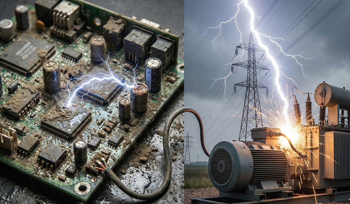
Equipment Damage and Operational Problems
Uncontrolled capacitor bank inrush current creates multiple problems affecting equipment life, system reliability, and power quality. These issues justify the engineering effort and equipment cost required to implement proper inrush current mitigation in accordance with industrial switchboard standards.
Switch and Contactor Damage
Circuit breakers, contactors, and disconnect switches used to energize capacitor banks experience severe electrical and mechanical stress from inrush current. The high di/dt (rate of current change) during switch closure generates electromagnetic forces between contact surfaces that can cause contact bounce—momentary opening and re-closing that produces multiple make-break cycles within milliseconds. Each bounce event generates a small arc that erodes contact material, gradually reducing contact area and increasing resistance.
Contact welding represents another failure mode where the high current density at contact surfaces generates sufficient heat to melt and fuse contact materials together, preventing the switch from opening when commanded. A real-world case involved a 150 kVAR capacitor bank in a cement plant that used a standard mechanical contactor rated only for motor starting duty. After approximately 500 switching cycles, the contactor contacts welded closed due to repeated inrush current stress, requiring emergency shutdown and contactor replacement. Proper specification of contactors for capacitor switching duty prevents this problem.
Fuse and Protection System Issues
Capacitor bank protection typically includes individual fuses for each capacitor element or unit to isolate failed components without de-energizing the entire bank. However, these fuses must withstand the high inrush current during energization without nuisance operation. Standard fast-acting fuses may clear on inrush current even when the capacitor bank operates normally, while slow-blow fuses might fail to protect during actual fault conditions.
Overcurrent relays and electronic protection devices face similar challenges. Instantaneous overcurrent elements must be set above peak inrush current to avoid false tripping, but this high setting may compromise fault protection sensitivity. Time-delayed overcurrent protection helps distinguish between brief inrush transients and sustained fault currents, but requires careful coordination with upstream protection. Modern microprocessor-based relays often incorporate inrush current restraint algorithms that recognize the characteristic high-frequency oscillation pattern and temporarily block tripping during energization.
Capacitor Element Degradation
The capacitor elements themselves suffer cumulative damage from repeated inrush current stress. Each energization subjects the dielectric material to high dV/dt stress that can initiate or propagate partial discharge activity at weak points in the insulation. Over thousands of switching cycles, this degradation accumulates, eventually leading to dielectric breakdown and element failure—often manifested as a short circuit that blows the internal or external fuse.
A food processing facility operating automatic capacitor banks to maintain power factor during varying production schedules documented premature capacitor failures after only 3 years of service, well short of the expected 15-year design life. Investigation revealed that the automatic controller switched capacitor stages 15 to 20 times per day to track load changes, accumulating 16,000 to 22,000 switching cycles. Without current-limiting reactors or controlled switching, each energization imposed full inrush stress on capacitor elements. After retrofitting current-limiting reactors, the facility achieved normal capacitor life expectancy.
Voltage Transients and Flicker
The sudden current surge during capacitor bank energization produces voltage transients on the power system that can affect other connected equipment. The voltage drop across system impedance during the inrush peak creates a momentary voltage dip at the capacitor bank connection point and nearby buses. Sensitive electronic loads such as variable frequency drives, programmable logic controllers, and computer systems may interpret these transients as faults and trip offline or reset.
Lighting systems, particularly gas-discharge lamps (fluorescent, metal halide, high-pressure sodium), exhibit visible flicker during capacitor switching as the voltage transient modulates light output. In commercial buildings and hospitals, occupants often complain about annoying flicker when automatic capacitor banks switch during normal operation. Compliance with IEC 61000 electromagnetic compatibility requirements limits these disturbances, driving the need for proper inrush current control.
Harmonic Generation and Power Quality
The high-frequency oscillatory component of inrush current contains harmonic content extending from hundreds of hertz to several kilohertz. These harmonics propagate through the power system, potentially exciting resonances with other inductive and capacitive elements. Harmonic resonance amplifies specific frequency components, creating sustained overvoltages or overcurrents at those frequencies even after the initial inrush transient decays.
In systems with power factor correction capacitors and variable frequency drives, capacitor bank switching transients can trigger nuisance trips of drive overvoltage protection. The drives’ DC bus capacitors and input reactors form resonant circuits with the power factor correction capacitors, and switching transients excite these resonances, causing temporary DC bus voltage rise that exceeds drive protection thresholds.
Methods for Calculating and Measuring Inrush Current
Accurate prediction and measurement of capacitor bank inrush current enables proper equipment specification and verification of mitigation effectiveness. Multiple approaches suit different stages of project development and available resources.
Further exploration of Inrush current can be found in the following recommended reading.
Theoretical Calculation Methods
For single capacitor bank energization from an infinite bus (negligible source impedance), a simplified equation provides approximate peak inrush current: I_peak ≈ V_peak × √(C/L_sys), where V_peak is system peak voltage, C is total capacitance, and L_sys is total system inductance. This formula assumes the capacitor switches on at voltage peak and neglects damping resistance.
For practical example, consider a 100 kVAR, 400V three-phase capacitor bank (approximately 1,990 µF per phase) connected through a cable and switchgear with total inductance of 20 µH. Peak voltage is 400 × √2 / √3 = 327V phase-to-neutral. Calculated peak inrush current: I_peak ≈ 327 × √(1,990×10⁻⁶ / 20×10⁻⁶) ≈ 327 × √99.5 ≈ 3,260 A. This represents approximately 65 times the rated current (50 A), indicating severe back-to-back switching conditions or very low system impedance.
More accurate calculations account for system resistance damping and actual switching instant relative to voltage waveform. These require solving differential equations describing RLC circuit transient response, typically performed using circuit simulation software.
Simulation Software Analysis
Circuit simulation programs such as PSCAD, EMTP-RV, MATLAB/Simulink, or ETAP allow detailed modeling of capacitor bank switching transients including accurate representation of system impedance, switching device characteristics, and control system timing. These tools simulate various switching scenarios—voltage peak, zero-crossing, back-to-back configurations—and predict peak inrush current, frequency content, and duration.
Engineers use simulation during design phases to evaluate different inrush mitigation strategies before equipment procurement. For example, simulation can compare current-limiting reactor values (3%, 6%, 10% reactance) and determine the minimum inductance required to limit inrush current below contactor ratings. Simulation also predicts harmonic resonance conditions and helps select reactor and capacitor values that avoid resonance at characteristic harmonic frequencies produced by nonlinear loads.
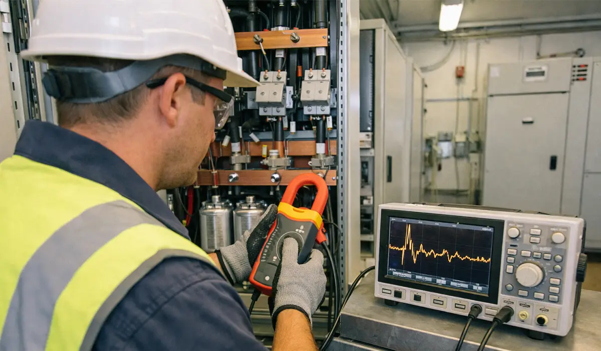
Field Measurement with Oscilloscopes
Oscilloscopes equipped with high-bandwidth current probes provide the most accurate field measurements of capacitor bank inrush current. Proper measurement technique requires selecting current probes rated for the expected peak current (often 1,000 to 5,000 A for capacitor switching) with sufficient bandwidth to capture the high-frequency oscillatory component (minimum 20 kHz bandwidth recommended). The oscilloscope must trigger on the rising edge of the inrush current waveform and capture at least 20 milliseconds of data to record the complete transient including decay.
Analysis of captured waveforms reveals peak current magnitude, oscillation frequency, decay time constant, and whether multiple peaks occur due to contact bounce or other switching anomalies. Comparing pre-mitigation and post-mitigation measurements quantifies the effectiveness of current-limiting reactors or controlled switching systems. Documentation requirements in NFPA 70E and IEEE 1584 arc flash standards may mandate inrush current measurements as part of system commissioning or incident investigation.
Peak-Reading Ammeter Measurements
Peak-reading digital multimeters and clamp meters offer simpler, lower-cost measurement alternatives when waveform detail is unnecessary. These instruments capture and hold the maximum instantaneous current value during a measurement period, providing a single number representing peak inrush current. However, they cannot distinguish between inrush current and other transients, provide no frequency information, and may miss very short-duration peaks if their sampling rate is insufficient.
Peak ammeters serve best for quick verification that mitigation measures reduce inrush below target values, or for routine maintenance checks confirming consistent switching performance over time. They cannot diagnose problems related to oscillation frequency, contact bounce, or harmonic content—these applications require oscilloscope measurements.
Proven Solutions for Reducing Capacitor Bank Inrush Current
Multiple engineering solutions effectively control capacitor bank inrush current, each with specific advantages, limitations, and appropriate applications. Selection depends on bank size, switching frequency, budget constraints, and required performance level while maintaining compliance with pollution degree and overvoltage category requirements.
Series Current-Limiting Reactors
Current-limiting reactors—air-core or iron-core inductors installed in series with capacitor bank phases—represent the most common inrush current mitigation method. The series inductance increases total circuit impedance during energization transients, limiting the rate of current rise (di/dt) and reducing peak current magnitude. Standard reactor ratings express inductance as a percentage of capacitive reactance: 3%, 6%, or 10% are typical values.
A 6% reactor means the inductive reactance equals 6% of the capacitive reactance at power frequency. For a 100 kVAR, 400V capacitor bank (capacitive reactance X_C ≈ 1.6 Ω), a 6% reactor provides 0.096 Ω inductive reactance, corresponding to approximately 300 µH inductance at 50 Hz. This inductance reduces inrush current to approximately 40% to 50% of the unrestricted value—from perhaps 2,000 A down to 800-1,000 A peak.
Additional benefits include harmonic filtering (the LC circuit formed by reactor and capacitor acts as a low-pass filter) and protection against back-to-back switching transients. Disadvantages include additional cost (reactors cost 15% to 30% of capacitor bank cost), increased physical space requirements, additional power losses (reactors dissipate perhaps 0.5% to 1% of bank rating), and slightly increased system voltage due to the voltage drop across reactor inductive reactance.
Installation of current-limiting reactors must comply with applicable standards regarding temperature rise, short-circuit withstand, and mounting provisions, with proper attention to IP and NEMA enclosure ratings for the installation environment.
| Current-Limiting Reactor Comparison | REACTOR RATING |
|---|---|
| Typical inrush reduction (% of unrestricted) | 40-60% |
| Standard inductance values: 3%, 6%, 10% | % of X_C |
| Additional cost (% of capacitor bank cost) | 15-30% |
| Power losses (% of bank rating) | 0.5-1.0% |
| Voltage rise due to reactor (% of nominal) | 3-10% |
| Harmonic filtering benefit | Yes |
| Protection against back-to-back switching | Partial |
| Maintenance requirements | Minimal |
Synchronous or Controlled Switching Systems
Synchronous switching systems use microprocessor-based controllers to close capacitor bank switching devices precisely at voltage zero-crossing, minimizing inrush current by avoiding high instantaneous voltage at switch closure. These systems measure system voltage waveform continuously, predict the next zero-crossing point, and issue closing command to the switch actuator with precise timing compensation for mechanical closing delay.
Modern vacuum circuit breakers offer closing time consistency within ±1 to ±2 milliseconds, and controlled switching systems compensate for this variation using adaptive algorithms that learn actual closing time from previous operations. When properly calibrated, controlled switching reduces inrush current to perhaps 20% to 30% of random-switching values—comparable to or better than current-limiting reactors but without added power losses or voltage rise.
A paper mill in Scandinavia retrofitted controlled switching to four 200 kVAR automatic capacitor banks that previously experienced frequent contactor failures from inrush stress. Post-retrofit measurements showed peak inrush reduction from 1,800 A to 450 A, extending contactor life from 18 months to over 5 years. The controlled switching system cost approximately 40% more than standard contactors but eliminated annual maintenance outages for contactor replacement, providing positive return on investment within 2 years.
Limitations include higher initial cost compared to standard switching equipment, dependence on accurate voltage measurement (voltage transformer failure disables controlled switching), and requirement for mechanical switching devices with consistent closing times (worn or maladjusted contactors degrade performance). Compliance with CE marking requirements for control panels ensures proper electromagnetic compatibility and safety interlocking.
Pre-Insertion Resistors
Pre-insertion resistor switching employs a two-stage closing sequence: first, the capacitor bank connects through a limiting resistor that restricts initial charging current; after the capacitor charges to near-system voltage (typically 20 to 50 milliseconds), a parallel bypass contactor closes to bypass the resistor and establish the final low-resistance connection. The resistor value is selected to limit inrush current to acceptable levels—typically 1 to 5 ohms for medium-voltage capacitor banks.
This technique effectively eliminates inrush current transients but introduces complexity through the two-stage switching mechanism and bypass contactor. The pre-insertion resistor must dissipate significant energy during the charging period, requiring adequate thermal capacity or cooling. Maintenance requirements increase because both main contacts and bypass contacts require periodic inspection. Pre-insertion resistor systems find primary application in high-voltage transmission capacitor banks (above 100 kV) where controlled switching technology faces challenges from voltage measurement accuracy and switch timing variability over very long switching distances.
Soft-Start Switching with Power Electronics
Thyristor-based soft-start controllers provide infinitely variable control of capacitor energization by phase-angle control or multi-step switching. These solid-state systems eliminate mechanical contacts and offer precise current limiting through controlled turn-on angle. However, their application in capacitor switching faces significant technical challenges: thyristors must block reverse voltage when capacitor voltage exceeds instantaneous system voltage, requiring series thyristor strings or special reverse-blocking devices; and losses in the thyristor forward voltage drop (1 to 2 V per device) create continuous power dissipation during normal operation.
Solid-state capacitor switching finds use primarily in specialized applications such as static VAR compensators (SVCs) for dynamic reactive power control in transmission systems, or high-speed switching applications where mechanical devices cannot operate quickly enough. Cost and complexity limit adoption in standard industrial power factor correction installations.
Hybrid Approaches
Some advanced installations combine multiple mitigation techniques to achieve optimal performance. For example, a large petrochemical facility uses 6% current-limiting reactors to provide baseline inrush reduction and harmonic filtering, combined with synchronous switching to further minimize transients during automatic capacitor bank operation. This hybrid approach reduced peak inrush current from 3,500 A (unprotected) to 650 A (reactors only) to 350 A (reactors plus synchronous switching), extending contactor life by a factor of 10 and eliminating voltage transient complaints from process control systems.
Compliance with International Standards
Proper capacitor bank design and inrush current mitigation must comply with relevant international and regional standards governing equipment ratings, installation practices, and safety requirements. Key standards include:
IEC 60831 and IEC 61921 specify performance requirements for shunt capacitors and capacitor banks for AC systems, including voltage ratings, capacitance tolerances, discharge device requirements, and marking requirements. These standards mandate that capacitors withstand certain levels of inrush current without damage, typically specified as withstanding 100 times rated current for 1 millisecond or 50 times rated current for 5 milliseconds.
IEEE Std 18 provides recommendations for shunt capacitor installation, addressing inrush current, switching device ratings, overcurrent protection, discharge devices, and grounding practices. The standard recommends current-limiting reactors or controlled switching when peak inrush current exceeds 50 times rated current in back-to-back configurations or when contactors experience reduced electrical life.
IEC 62271-100 and IEEE C37.012 cover high-voltage circuit breakers for capacitor switching duty, specifying test requirements demonstrating that breakers can interrupt capacitor current and withstand inrush current without contact welding or excessive erosion. Breaker ratings must be verified for the specific capacitor bank configuration, including back-to-back switching scenarios.
Regional variations include AS/NZS 61439 standards for low-voltage assemblies in Australia and New Zealand, which adopt IEC requirements with local modifications. Compliance with ATEX and IECEx requirements becomes necessary for capacitor banks installed in hazardous areas where explosive atmospheres may be present.
Real-World Case Studies
Case Study 1: Automotive Manufacturing Plant
A 250,000 square-foot automotive parts manufacturing facility in Germany experienced repeated failures of automatic power factor correction contactors, requiring replacement every 6 to 9 months at a cost of €1,200 per contactor plus production downtime for maintenance. The facility operated three 150 kVAR capacitor banks connected to the 400V main distribution bus, with an automatic controller switching banks 10 to 15 times daily to maintain power factor above 0.95 as welding robots and forming presses cycled on and off.
Investigation revealed that the original system design specified standard motor-duty contactors rather than capacitor-switching-duty contactors, and included no current-limiting reactors or controlled switching. Oscilloscope measurements documented peak inrush currents ranging from 1,400 to 2,800 A depending on switching instant—well beyond the 800 A switching capacity of the installed contactors.
The engineering solution replaced contactors with properly-rated devices and installed 6% current-limiting reactors on each capacitor bank. Post-modification measurements showed peak inrush reduced to 450 to 600 A, well within contactor ratings. After 3 years of operation under this configuration, contactors showed minimal contact wear and continued reliable service. Total retrofit cost of €18,000 paid back within 18 months through eliminated maintenance costs and avoided production losses.
Case Study 2: Hospital Critical Power System
A 400-bed hospital in the United States installed a 300 kVAR automatic capacitor bank on the 480V main electrical service to reduce utility demand charges. Shortly after commissioning, the facility experienced unexplained shutdowns of medical imaging equipment (CT scanners and MRI systems) coinciding with capacitor bank switching events. Investigation by equipment vendors initially suspected imaging equipment defects, but comprehensive testing found the equipment operating within specifications.
Power quality monitoring revealed that capacitor bank energization created voltage transients exceeding ±10% of nominal voltage at the imaging equipment connections, despite the equipment being separated from the capacitor bank by 150 feet of building distribution. The uncontrolled inrush current (measured at 2,100 A peak) produced voltage drop across building impedance that triggered voltage-sag ride-through limits in the imaging equipment power supplies, causing system resets.
The solution implemented synchronous switching control to minimize inrush transients, reducing peak current to 380 A and voltage transient magnitude to ±3% of nominal. Additionally, a 7% current-limiting reactor provided further reduction and harmonic filtering. The combined mitigation system cost $22,000 but eliminated equipment shutdowns that had resulted in delayed patient procedures, regulatory reporting requirements, and potential safety incidents. The hospital maintained compliance with electrical safety standards while achieving desired power factor improvement.
Conclusion and Recommendations
Capacitor bank inrush current represents a manageable engineering challenge when properly addressed through appropriate design, equipment selection, and mitigation techniques. Ignoring this phenomenon leads to premature equipment failures, increased maintenance costs, power quality problems, and potential safety hazards. The fundamental physics—rapid charging of capacitance through low impedancecannot be eliminated, but its effects can be controlled through proven methods.
Critical factors determining inrush severity include capacitor bank size, system impedance, switching instant relative to voltage waveform, back-to-back configurations, and residual voltage. These factors interact, sometimes amplifying inrush to 50 to 100 times rated current in worst-case scenarios. Consequences include accelerated contact wear, fuse nuisance operation, voltage transients affecting sensitive loads, and premature capacitor element failure.
Effective mitigation strategies—current-limiting reactors, synchronous switching systems, pre-insertion resistors, or hybrid combinations—reduce inrush current to acceptable levels determined by switching device ratings and system power quality requirements. Selection depends on economic analysis balancing initial equipment cost, operating losses, maintenance requirements, and expected equipment life.
For procurement of high-quality capacitor banks, current-limiting reactors, controlled switching systems, and related components meeting international standards, consult with specialized manufacturers and verify compliance documentation including type test reports, IEC 62271-200 arc fault test reports, and quality management certifications. Proper earthing system design also contributes to overall installation safety and performance.
Frequently Asked Questions
What is capacitor bank inrush current?
Capacitor bank inrush current is a sudden, high-magnitude current surge that occurs when a capacitor bank connects to an energized electrical system. At the moment of switch closure, an uncharged capacitor presents near-zero impedance and behaves temporarily as a short circuit, drawing extremely high current (typically 10 to 20 times rated current, sometimes higher in back-to-back configurations) as it charges from zero volts to system voltage within a few milliseconds. This transient current exhibits high-frequency oscillatory characteristics and decays rapidly as the capacitor charges and steady-state conditions establish.
Why does a capacitor behave like a short circuit at the moment of connection?
An uncharged capacitor initially presents zero voltage across its terminals, meaning zero impedance to the initial current flow when connected to an energized system. The fundamental capacitor relationship i = C(dV/dt) shows that to change capacitor voltage rapidly (high dV/dt), a large current must flow. At the instant of energization, system voltage applies across an uncharged capacitor, creating theoretically infinite dV/dt and therefore theoretically infinite current—in practice limited only by circuit resistance and inductance to finite but very high values. This behavior persists only for the first few milliseconds until the capacitor charges to near system voltage and impedance rises to normal capacitive reactance value.
How large can inrush current be compared to rated current?
Single capacitor bank energization from a relatively stiff power system typically produces peak inrush current 10 to 20 times the steady-state rated current. For example, a 100 kVAR capacitor bank with 144 A rated current might experience 1,440 to 2,880 A peak inrush. However, back-to-back switching configurations—where an already-energized capacitor bank partially discharges into a newly-connected bank—can generate inrush current 50 to 100 times rated current. The exact multiplier depends on system impedance, switching instant relative to voltage waveform, capacitor bank configuration, and presence of current-limiting devices.
Why does switching at voltage peak increase inrush current?
Switching at voltage peak applies maximum instantaneous voltage (±√2 times RMS voltage, or approximately ±565V in a 400V line-to-line system) across the uncharged capacitor at switch closure. This maximum voltage drives maximum current through the circuit impedance according to Ohm’s law: I = V/Z. Conversely, switching at voltage zero-crossing means the system voltage is passing through zero volts at switch closure, so initially zero voltage applies across the uncharged capacitor (which also has zero volts), resulting in zero initial current. As voltage rises from zero following the natural AC waveform, current flows to charge the capacitor but at a controlled rate limited by circuit impedance, producing much lower peak current than peak-voltage switching.


