
Busbar fabrication machines transform raw copper and aluminum materials into precisely configured busbars that serve as the electrical backbone of industrial control panels, switchgear assemblies, and power distribution networks. Understanding busbar fabrication provides valuable insight into the complete manufacturing process. As electrical infrastructure demands escalate across renewable energy, data centers, and industrial automation, selecting and optimizing busbar fabrication equipment has become critical for manufacturers seeking competitive advantage through production efficiency and quality consistency.
Busbar Fabrication Machines Overview
Busbar fabrication machines are specialized metalworking equipment designed to perform precision cutting, punching, and bending operations on conductive metal strips used in electrical power distribution. Modern equipment ranges from manual hydraulic presses requiring skilled operators to sophisticated CNC-controlled systems executing complex sequences with minimal human intervention. Understanding the different types of busbar fabrication machines helps manufacturers select equipment matching their specific operational requirements. The evolution from manual to automated systems has revolutionized busbar manufacturing, enabling manufacturers to achieve previously unattainable levels of precision, consistency, and production throughput.
These machines serve diverse industries and applications. Electrical panel builders utilize them to produce customized busbars for industrial control systems, motor control centers, and distribution boards. Switchgear manufacturers depend on high-capacity processing equipment to fabricate busbars handling currents from hundreds to thousands of amperes in low and medium voltage installations. These electrical workhorses power across modern industrial facilities. The renewable energy sector employs busbar fabrication technology extensively for solar inverter systems, wind turbine power electronics, battery energy storage systems, and charging infrastructure for electric vehicles. Data center operators require precisely manufactured busbars for high-density power distribution supporting server infrastructure, cooling systems, and backup power installations.
The technical complexity of busbar fabrication arises from the demanding requirements these components must satisfy. Busbars typically operate under continuous high-current loads often exceeding 1,000 amperes in industrial applications, with peak currents during startup or fault conditions reaching several times nominal ratings. The physical tolerances for hole positioning, bend angles, and surface finish directly impact electrical performance, thermal management, and mechanical integrity of the complete electrical installation. Misaligned holes prevent proper mounting in electrical enclosures, forcing technicians to improvise connections that compromise safety and performance. Excessive burrs from punching operations create potential arc points and safety hazards that can lead to equipment failure or fire. Inconsistent bend angles result in poor fit and assembly difficulties, increasing installation time and labor costs.
Material properties further complicate the fabrication process. Copper, the predominant busbar material, exhibits excellent electrical conductivity enabling more compact installations compared to aluminum alternatives. However, copper’s ductility and work-hardening characteristics require substantial force for cutting and forming operations. A 10mm thick, 120mm wide copper busbar requires punching forces exceeding 40 tons for creating standard M12 connection holes. Aluminum offers advantages in weight reduction and lower material costs but demands different processing parameters and tooling configurations to prevent material deformation and achieve acceptable edge quality. Manufacturers should consider the key benefits of aluminum busbars when evaluating material options for specific applications. Many manufacturers maintain capability to process both materials, requiring equipment versatility and operator expertise in managing material-specific requirements.
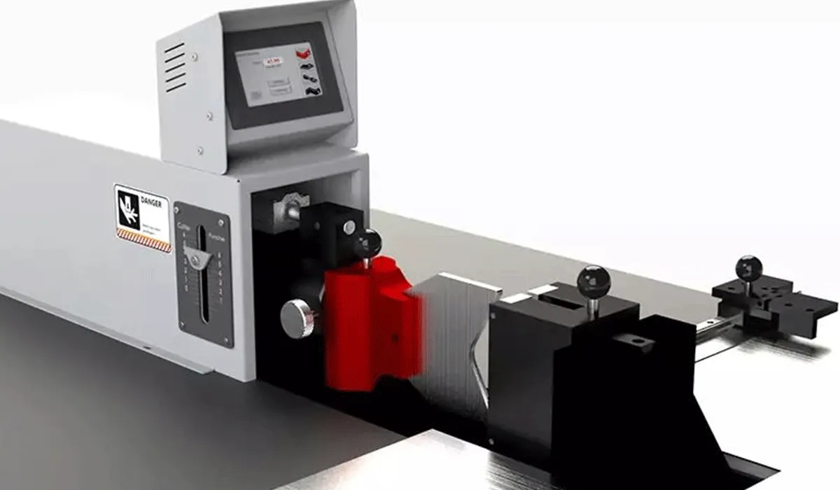
Busbar Cutting Machines
Busbar cutting machines represent the critical first operation in busbar fabrication, determining the precision and efficiency with which raw material stock is converted into dimensionally accurate blanks ready for subsequent punching and bending operations. These specialized systems must deliver clean, perpendicular cuts without introducing edge deformation, burrs, or work hardening that would compromise downstream processing or final electrical performance.
Hydraulic shearing systems constitute the most prevalent cutting technology for busbar fabrication. These machines employ a hardened steel blade moving vertically against a fixed blade, creating a shearing action that separates the material cleanly. The cutting force generated by the hydraulic system must overcome the shear strength of the busbar material—copper busbars with 10mm thickness and 120mm width require approximately 30-35 tons of cutting force. Advanced hydraulic shear systems incorporate programmable back gauges enabling precision length positioning with repeatability within ±0.1mm, essential for producing consistent busbar lengths in production environments where dimensional accuracy directly affects assembly efficiency.
Blade geometry and maintenance state significantly influence cut quality and operational costs. Properly maintained blades with correct clearance settings (typically 5-10% of material thickness) produce clean cuts with minimal burr formation, reducing or eliminating secondary deburring operations. Dull or incorrectly adjusted blades generate excessive burrs requiring additional finishing work, increased material waste, and potential damage to the busbar surface that can create electrical performance issues. Understanding how to overcome common challenges in busbar fabrication helps operators maintain optimal equipment performance. Leading manufacturers implement blade condition monitoring systems that track cut counts and cutting force trends, providing predictive alerts before blade deterioration affects production quality, enabling planned blade replacement during scheduled maintenance rather than emergency repairs during production runs.
Guillotine-style cutting machines offer an alternative approach particularly suited for heavier busbar sections and high-volume production operations. These robust systems employ a blade descending at an angle, progressively cutting through the material from one edge to the opposite. This angled cutting action distributes cutting forces more gradually, reducing shock loads on the machine structure and extending blade service life compared to straight shearing designs. Modern guillotine cutters process copper busbars up to 15mm thick and 200mm wide, with production rates exceeding 60 cuts per hour when equipped with automated material feeding systems that eliminate manual material handling between cuts.
CNC Busbar Cutting Machines
CNC (Computer Numerical Control) busbar cutting machines represent the technological frontier in precision busbar fabrication, integrating automated material handling, servo-controlled cutting mechanisms, and sophisticated software control to achieve unprecedented levels of accuracy, repeatability, and production throughput. These advanced systems transform busbar cutting from a manual, operator-dependent process into a highly automated operation capable of executing complex cutting sequences with minimal human intervention, dramatically improving both productivity and quality consistency.
The fundamental architecture of CNC cutting systems centers on precision linear motion control. Servo motors coupled with ball screw mechanisms position the cutting tool or material with resolution typically exceeding 0.01mm. Absolute position encoders continuously monitor actual position, enabling closed-loop control that compensates for mechanical backlash, thermal expansion, and load-induced deflection. This precision positioning capability proves essential for applications requiring tight dimensional tolerances—electrical busbars for precision electronic equipment often specify length tolerances of ±0.05mm to ensure proper fit within constrained assembly spaces where even minor dimensional variations prevent successful installation.
Material handling automation significantly enhances CNC cutting system productivity and operational efficiency. Automatic loading systems retrieve busbar stock from material racks, position it in the cutting area, and present it to the cutting mechanism without operator handling, eliminating the time and labor associated with manual material movement. Following each cut, the finished piece is either stacked in an output bin or transferred to downstream processing equipment via conveyor systems, while skeleton (scrap) material is automatically segregated for recycling. A fully automated CNC cutting line can maintain continuous operation for extended periods, processing hundreds of pieces per shift with consistent quality and minimal operator intervention, enabling lights-out manufacturing during unattended shifts.
Software integration extends CNC cutting capabilities beyond simple position control to comprehensive production management. Modern systems accept cutting programs directly from CAD/CAM software or ERP systems, eliminating manual program entry and associated transcription errors that can result in scrap production or rework. Harnessing the power of advanced machinery enables manufacturers to maximize productivity and quality. Nesting algorithms optimize material utilization by arranging multiple cutting patterns to minimize waste—particularly valuable when processing expensive copper stock where material costs represent 60-70% of total busbar manufacturing expenses. Production tracking features log every cut operation, recording dimensional measurements, cutting forces, and blade condition data that supports quality assurance programs and continuous improvement initiatives by identifying trends and opportunities for process optimization.
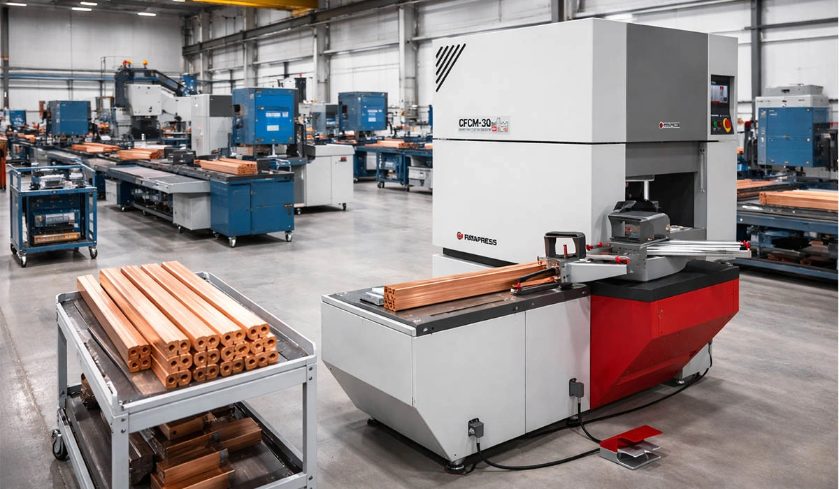
| HBC-CP.CNC200 | MODEL |
|---|---|
| Cutting and punching busbars simultaneously | Function |
| Up to 200 x 15 mm | Cutting capacity |
| Busbar size: 200 x 15 mm Circle dies: M6 UP M20 | Punching capacity |
| CNC controller | Puncher center finder |
| Ball Screw and Servo Motors | Length measuring in puncher and cutter |
| One Power Pack, Double Acting System | Hydraulic system |
| 400 (KN) | Max Force |
| 200 Bar | Operating pressure |
| 1 x 11 Kw | Power rating |
| 380 Volt – 3/50 Hz | Voltage |
| Hydraulic oil H68 – 290 liters | Oil |
| 537 x 240 x 188 (H) cm | Main desk dimension |
3 in 1 Busbar Machines (Cut, Punch, Bend)
Three-in-one busbar fabrication machines represent a versatile and cost-effective solution for manufacturers requiring complete busbar processing capabilities within a single, integrated platform. These multifunctional systems combine cutting, punching, and bending operations in a unified machine structure, enabling operators to execute all primary busbar fabrication processes without transferring workpieces between separate specialized machines. The benefits of combining multiple functions extend beyond simple convenience to deliver measurable improvements in productivity and quality. This integration offers substantial benefits in terms of floor space utilization, capital investment efficiency, and operational simplicity, making 3-in-1 machines particularly attractive for small to medium-sized manufacturers, job shops, and facilities with diverse product requirements that demand operational flexibility.
The architectural design of 3-in-1 machines centers on a common hydraulic power pack serving multiple processing stations. In basic configurations, a single hydraulic pump and valve system sequentially powers cutting, punching, and bending functions through operator-controlled valve selection. More advanced models incorporate multiple independent hydraulic circuits enabling simultaneous operation of different stations—for example, one operator can perform punching operations while a second operator executes bending on a separate workpiece, effectively multiplying machine productivity without requiring additional floor space or capital investment in separate machines.
The HBC-A120 ES/EH exemplifies the sophisticated evolution of 3-in-1 machine design, incorporating three independent hydraulic power units that enable true simultaneous operation of cutting, punching, and bending stations. This parallel processing capability allows three operators to work concurrently on different operations, effectively tripling throughput compared to sequential operation modes found in basic 3-in-1 designs. The machine processes copper and aluminum busbars up to 120mm wide and 12mm thick, suitable for switchgear applications handling currents up to approximately 800 amperes, covering a substantial portion of industrial electrical installation requirements. Programmable length stops on all three stations ensure dimensional consistency across production runs, while Industry 4.0 connectivity enables remote monitoring and production data collection supporting continuous improvement initiatives and integration with enterprise manufacturing systems.
Key Advantages of 3-in-1 Busbar Machines:
- Reduced floor space requirements compared to three separate machines—typical footprint of 5-6 square meters versus 15-20 square meters for dedicated cutting, punching, and bending equipment
- Lower total capital investment—single 3-in-1 machine costs 40-60% less than purchasing separate cutting, punching, and bending machines with equivalent capacity
- Simplified operator training—technicians learn operation of one integrated system rather than three separate machines, reducing training time and cross-training complexity
- Reduced material handling—workpieces remain on the machine throughout all processing operations, eliminating inter-machine transport that consumes time and risks damage
- Quick changeover between operations supports flexible, responsive production scheduling ideal for small batch production and custom fabrication work
Workshop Busbar Processing Machines
Workshop busbar processing machines occupy a specialized niche addressing the unique requirements of field service operations, maintenance departments, and small fabrication shops where portability, compact footprint, and operational versatility take precedence over maximum processing capacity or automation sophistication. These machines embody a fundamentally different design philosophy from production-oriented systems, emphasizing rugged construction suitable for non-ideal operating environments, quick setup capability for diverse applications, and the ability to handle various tasks beyond standard busbar fabrication that are commonly encountered in field service and maintenance work.
The defining characteristic of workshop machines is their portable, self-contained design enabling deployment flexibility. Integrated wheeled bases or compact dimensions enable movement by hand truck or small forklift, allowing deployment wherever work is required rather than requiring workpiece transport to a fixed machine location in a centralized facility. This mobility proves invaluable in retrofit and service applications—for example, a maintenance technician servicing an industrial facility can bring a workshop machine directly to the electrical room, fabricating replacement busbars on-site using measurements taken from the installed equipment, eliminating the time delays inherent in off-site fabrication and potential measurement errors that occur when trying to replicate existing installations from field measurements alone.
The HBC-PC120 portable workshop busbar machine exemplifies this category, providing integrated cutting, punching, and bending capabilities in a compact, transportable format suitable for diverse working environments. The machine’s single hydraulic power unit operates all functions through quick-change tooling heads, enabling an operator to reconfigure from cutting to punching or bending operations within 30-60 seconds through a simple head exchange procedure. While this sequential operation mode results in lower throughput compared to machines with simultaneous processing capability utilizing multiple power units, the trade-off proves acceptable in workshop environments where job variety, setup flexibility, and equipment portability matter more than maximum production rate measured in pieces per hour.
Extended functionality enhances workshop machine utility beyond pure busbar fabrication, making these machines valuable multi-purpose tools for electrical contractors and maintenance operations. Cable crimping capability up to 300mm² accommodates termination of large power cables to busbars, eliminating the need for separate crimping equipment that would require additional capital investment and consume precious truck or workshop space. Cable cutting functions handle conductors up to 240mm², supporting complete electrical assembly operations from a single machine platform. This multifunctionality proves particularly valuable in field service applications where technicians must carry minimal equipment while maintaining capability to address diverse tasks encountered during installation, modification, or maintenance work on electrical systems.
CNC Busbar Processing Centers
CNC processing centers represent the apex of busbar fabrication technology, integrating multi-axis servo control, automated tool changing, vision systems, and comprehensive software connectivity. These systems demonstrate the global impact of busbar machines on switchgear panel in modern electrical installations. Five-axis configurations enable complex hole patterns and compound bends without manual reorientation. Tool magazines holding 20-40 different tools execute complete processing sequences incorporating diverse operations with 3-5 second automatic tool changes.
Vision systems and measurement probes enable in-process verification. Laser measurement scans incoming stock, determining actual dimensions and automatically adjusting processing parameters to maintain final dimensions within specification. Robotic loading retrieves material from vertical storage, while finished parts transfer to inspection or packaging. Direct CAD/CAM integration generates CNC programs without manual effort, while ERP integration links operation to production scheduling.
| Feature | Standard 3-in-1 | CNC Processing Center |
|---|---|---|
| Positioning Accuracy | ±0.5mm (manual) | ±0.02mm (servo) |
| Setup Time | 15-30 minutes | 3-5 minutes |
| Production Rate | 15-25 pieces/hour | 60-120 pieces/hour |
| Tool Changing | 5-10 minutes | 3-5 seconds |
| Quality Consistency | Variable | Excellent |
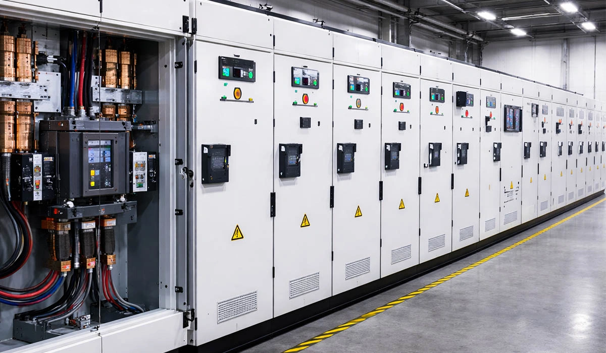
Busbar Fabrication Machines for LV Switchgear
Low voltage (LV) switchgear applications—systems operating at voltages up to 1,000 VAC or 1,500 VDC—represent the largest market segment for busbar fabrication equipment, encompassing industrial control panels, motor control centers, distribution boards, and power distribution units serving commercial and industrial facilities worldwide. Busbar fabrication machines serving this market must balance several competing requirements: adequate processing capacity for the relatively moderate busbar dimensions typical of LV applications, precision sufficient to meet assembly tolerances in increasingly compact enclosures, and cost-effectiveness appropriate for the competitive pricing pressures characterizing the LV switchgear market where manufacturers compete intensely on both quality and price.
LV switchgear busbars typically range from 3mm to 12mm thickness and 30mm to 150mm width, with copper predominating due to its superior conductivity enabling more compact installations that minimize enclosure size and cost. Current ratings span from 100 amperes in small distribution boards serving lighting and general-purpose circuits to 5,000 amperes in main distribution centers serving large industrial facilities with extensive electrical loads. These dimensional parameters align well with the capabilities of mid-range busbar fabrication equipment—3-in-1 machines rated for 120mm x 12mm material handle the vast majority of LV applications encountered in typical industrial and commercial installations, while larger systems rated for 200mm x 15mm provide capacity for the most demanding LV switchgear installations serving major industrial processes or large commercial buildings.
Hole pattern precision directly impacts LV switchgear assembly efficiency and final product quality. Standardized mounting hole spacing—commonly 200mm, 400mm, or 600mm intervals corresponding to panel enclosure mounting rails specified by IEC and NEMA standards—requires positioning accuracy within ±0.3mm to ensure busbars align properly with mounting hardware without forcing or improvisation during assembly. Connection hole positioning for circuit breaker and contactor terminals demands similar precision; misaligned holes force technicians to improvise connections using oversized washers or drilling additional holes, compromising electrical performance, safety compliance, and installation aesthetics. Advanced 3-in-1 machines with programmable positioning or CNC processing centers readily achieve these tolerances consistently across production runs, while basic manual machines require skilled operators and careful setup procedures to maintain acceptable quality levels.
Production volume considerations in LV switchgear manufacturing strongly influence appropriate equipment selection and capital allocation decisions. Large manufacturers producing standardized switchgear products in volumes exceeding 10,000 panels annually justify investment in automated CNC processing centers that maximize throughput, quality consistency, and labor efficiency while supporting the documentation and traceability requirements increasingly demanded by customers in regulated industries. Medium-volume manufacturers assembling 2,000-5,000 panels yearly typically optimize costs and capabilities through advanced 3-in-1 machines balancing automation features and operational flexibility suitable for moderate product variety. Small panel builders and custom switchgear shops handling fewer than 1,000 assemblies annually often achieve best economics with basic 3-in-1 or workshop machines, accepting lower throughput and requiring greater operator skill to minimize capital investment that would be difficult to justify at modest production volumes.
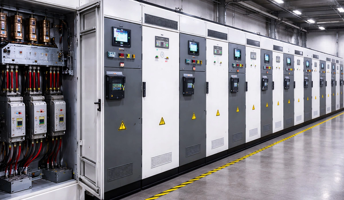
Busbar Fabrication Machines for MV Panels
Medium voltage (MV) switchgear applications—systems operating at voltages from 1kV to 35kV—impose substantially more demanding requirements on busbar fabrication equipment compared to low voltage applications, driven by the elevated electrical stresses and safety considerations inherent in higher voltage operation. The elevated voltages and currents typical of MV installations necessitate larger busbar cross-sections to handle increased power levels, more stringent surface finish requirements to prevent partial discharge and electrical breakdown, and enhanced dimensional precision to maintain electrical clearances mandated by safety standards and ensure safe, reliable long-term operation in critical power distribution applications.
MV switchgear busbars typically range from 10mm to 20mm thickness and 100mm to 250mm width, with some high-current applications employing even larger sections or multiple busbars arranged in parallel configurations to achieve required current capacity. Copper remains predominant despite significantly higher material costs compared to aluminum due to its superior current density enabling more compact installations—a critical advantage in space-constrained utility substations and industrial power distribution centers where real estate costs and physical space limitations strongly favor compact equipment designs. Processing these massive sections demands substantial force capability; punching an M20 connection hole through a 200mm x 15mm copper busbar requires forces exceeding 60 tons, while cutting operations demand 50-70 tons of shearing force. Standard busbar fabrication machines lack adequate capacity for these heavy-duty operations, necessitating specialized equipment specifically designed and constructed for demanding MV applications.
Surface finish quality assumes critical importance in MV applications due to the elevated electrical field strengths present at higher voltages that can initiate electrical breakdown at surface imperfections. Sharp edges, burrs, or surface irregularities create localized field concentrations that can initiate partial discharge activity—electrical breakdown occurring in air gaps or insulation systems that does not immediately cause complete failure but progressively degrades equipment through chemical decomposition and material erosion, ultimately leading to catastrophic failure after months or years of operation. MV busbar fabrication therefore requires precision cutting and punching operations producing smooth edges with minimal burr formation, often followed by secondary finishing operations including deburring with specialized tools, edge rounding to eliminate sharp corners, and surface polishing to achieve smooth finishes. Advanced fabrication equipment incorporates these finishing operations within integrated processing sequences, ensuring consistent quality without requiring separate manual operations that introduce variability and increase labor costs.
Dimensional tolerances for MV busbars reflect the stringent electrical clearance requirements mandated by IEC 61936-1 and other applicable safety standards. These standards specify minimum phase-to-phase and phase-to-ground clearances based on voltage level and atmospheric conditions—for example, 12kV switchgear requires minimum clearances of 125mm in controlled indoor environments, with larger clearances required for outdoor installations or locations with contaminated atmospheres. Busbar positioning within these clearance envelopes must account for mechanical tolerances in mounting structures and thermal expansion under load conditions that can cause dimensional changes, often necessitating hole positioning accuracy within ±0.1mm and bend angle precision within ±0.5° to ensure adequate clearances are maintained under all operating conditions. CNC processing centers with closed-loop servo control readily achieve these demanding tolerances consistently across production runs, while manual or semi-automated equipment requires extraordinary operator skill and meticulous setup procedures difficult to maintain in production environments.
Busbar Fabrication Machine Selection by Capacity
Capacity selection must align machine capabilities with current demands and anticipated growth. Maximum dimensional capacity establishes baseline criteria. Standard tiers reflect common applications: 120mm x 10mm addresses most LV control panels (up to 800A), 200mm x 15mm covers virtually all LV and medium-current MV applications (up to 12kV), and 250mm x 20mm serves high-current MV and specialized industrial power distribution.
Throughput analysis requires evaluating product mix complexity. A facility producing 500 identical busbars monthly requires different equipment than a custom shop fabricating 500 diverse configurations. Conservative sizing based solely on current production creates expansion barriers. Industry best practice suggests sizing for 150-200% of current volume when growth is anticipated, providing headroom while avoiding excessive over-capacity.
| Monthly Production | Recommended Equipment | Key Factors |
|---|---|---|
| 0-200 busbars | Economic 3-in-1 or Workshop | Low investment, simplicity |
| 200-800 busbars | Standard 3-in-1 | Balance capability and cost |
| 800-2,000 busbars | Advanced 3-in-1 or Entry CNC | Automation reduces labor |
| 2,000-5,000 busbars | CNC Processing Center | Automation essential |
| 5,000+ busbars | Multiple CNC Centers | Maximum efficiency |
Copper Busbar Bending Machines
Copper busbar bending represents the most technically challenging operation, requiring precise force control while managing work-hardening characteristics and achieving dimensional accuracy in three-dimensional geometries. Advanced busbar bending techniques enable manufacturers to produce complex geometries while maintaining quality and precision. Bending involves plastic deformation around forming tools while constraining material to prevent twisting or wrinkling. The neutral axis shifts based on bend radius and material properties—material on the outside radius stretches and thins while inside material compresses.
Bend radius selection critically influences manufacturability and electrical performance. Tight radii (1-2x thickness) enable compact routing but require higher forces and risk cracking. Conservative radii (3-4x thickness) reduce manufacturing difficulty but consume more space. IEC standards recommend minimum 2.5x thickness for copper, balancing manufacturing and reliability. Spring-back compensation proves critical—copper exhibits 2-5° spring-back for 90° bends. CNC systems incorporate models automatically calculating required over-bend angles achieving targets within ±0.5°.
Busbar Fabrication Line Layout and Workflow
Optimizing facility layout and workflow determines overall manufacturing efficiency, quality consistency, and operator satisfaction. Thoughtful arrangement minimizes material handling, reduces work-in-process inventory, and creates ergonomic environments. Linear workflow arrangements prove most effective for high-volume dedicated production—material flows sequentially through cutting, punching, bending, finishing, inspection, and packaging stations, minimizing backtracking.
Cellular layouts suit custom operations handling diverse products with variable sequences. Equipment clusters around central staging areas with operators moving between stations as required. This maximizes flexibility but consumes larger floor space (60% utilization versus 75-80% for linear). Quality control positioning significantly influences defect detection timing—inspection immediately following cutting catches dimensional errors before adding value through punching and bending.
For more detailed insights into Line Layout, this article is highly recommended.
Tooling and Dies for Busbar Fabrication Machines
Tooling represents critical consumables directly determining quality, productivity, and costs. Punching tools employ high-speed steel (HSS) for standard applications or carbide for extended life. HSS tools suit moderate volumes, delivering 50,000-100,000 hits before resharpening. Carbide tools cost 3-5x more but provide 200,000-500,000 hits, economical for high-volume production.
Punch-die clearance critically affects hole quality and tool life. Insufficient clearance (<3% material thickness) causes excessive friction and rapid wear. Excessive clearance (>10%) produces ragged holes with pronounced burrs. Optimal clearance typically measures 5-8% for copper. Regular inspection identifying worn tools before catastrophic failure prevents defective production. Preventive resharpening after 70-80% expected life restores performance while maintaining dimensional accuracy.
To deepen your knowledge of Selection Guide busbar, reading this article is a great option.
Busbar Machine Accuracy and Repeatability
Accuracy describes how closely output matches commanded dimensions, while repeatability measures consistency across multiple operations. Superior repeatability often proves more valuable than absolute accuracy since consistent offsets can be compensated through programming, while random variation cannot. CNC systems with closed-loop servo positioning achieve repeatability within ±0.02mm, far exceeding manual machines where variation depends entirely on operator skill (±0.3-0.5mm).
Environmental factors significantly affect precision. Temperature variations cause expansion/contraction—5°C temperature change induces 0.06mm dimensional change in 1-meter steel beds. Professional installations maintain 20±2°C ambient conditions and vibration-isolated foundations. Periodic calibration using precision standards—typically annually or after 50,000-100,000 pieces—identifies accuracy degradation requiring adjustment.
Busbar Machine Maintenance and Troubleshooting
Systematic maintenance maximizes uptime, service life, and quality while minimizing unplanned downtime and repair costs. Preventive maintenance establishes routine tasks performed at regular intervals. Daily tasks include visual inspection for leaks, checking hydraulic oil level, removing debris, and verifying safety functions. Weekly tasks add lubrication and tool inspection. Monthly maintenance incorporates hydraulic oil sampling, electrical inspection, and calibration verification. Annual service involves complete hydraulic service and comprehensive electrical testing.
Reading this article will give you a deeper insight into Troubleshooting.
Hydraulic system maintenance deserves particular attention. Contaminated oil causes premature component wear while degraded oil provides inadequate lubrication. Oil sampling every 6-12 months identifies contamination and degradation before problems develop. Maintaining temperature below 60°C extends oil life and prevents accelerated wear. Common problems include excessive burr formation (indicating dull tools or incorrect clearance), inconsistent bend angles (worn dies or pressure variation), and accuracy degradation (positioning backlash or thermal expansion).


Busbar fabrication machines make production much more precise and efficient. They help reduce manual work, improve consistency, and support faster manufacturing in electrical projects.