
Electrical panel equipment and components refer to an integrated system of interconnected electrical devices working in coordination to achieve specific control, protection, and distribution purposes. These components include protective devices, switches, contactors, measuring instruments, transformers, conductors, and busbars—all designed to minimize risks to personnel and installations while ensuring reliable, uninterrupted operation. Proper selection based on engineering principles and compliance with IEC standards is essential to prevent hazards such as overload fires, short circuits, and equipment damage.
Alternatively, an audio version of this article is available below for your convenience.
What is an Electrical Panel?
An electrical panel is a protected enclosure housing electrical equipment designed to control, distribute, and protect electrical circuits and systems. Originally, electrical installations were open, exposing operators to live parts and environmental hazards. To address safety concerns arising from equipment installation, environmental factors, short circuits, and operator access to energized components, manufacturers developed closed panel enclosures that shield internal components while maintaining functionality.
Modern electrical panels serve as the nerve center for industrial facilities, commercial buildings, and infrastructure projects. They house a comprehensive array of devices that work together to manage power distribution, provide circuit protection, enable load control, and facilitate monitoring of electrical parameters. The evolution of panel design has progressed from simple fuse boxes to sophisticated systems incorporating digital monitoring, remote diagnostics, and intelligent protection schemes.
Critical Safety Principle: Selecting the type, rated value, and breaking capacity of protective devices in a circuit is mandatory to prevent hazards such as overload fires and short circuits caused by system faults. Supervisors must pay special attention during installation and commissioning. Any conductor assembly including cable, busbar, and wire, along with related protections and insulation, must be designed and manufactured according to IEC standards to prevent injury and property damage.
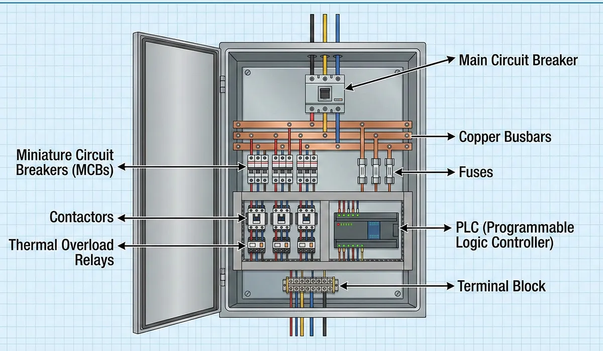
Essential Electrical Panel Components
Electrical panel components can be categorized into several functional groups, each serving specific purposes within the overall system. The most important electrical panel equipment and components include automatic circuit breakers (molded case circuit breakers), miniature circuit breakers (MCBs), residual current devices (RCDs), contactors, thermal overload relays, bimetallic protectors, push button stations, air circuit breakers, phase monitoring relays, time relays, programmable logic controllers (PLCs), variable frequency drives (inverters), soft starters, various sensors, and signal lamps for indication and warning.
Primary Component Categories
- Protection Devices: Circuit breakers, fuses, RCDs, earth fault relays
- Control Devices: Contactors, relays, timers, PLCs, smart relays
- Switching Devices: Disconnectors, load switches, selector switches
- Measuring Instruments: Ammeters, voltmeters, power meters, energy analyzers
- Transformers: Current transformers (CT), potential transformers (PT), CBCTs
- Conductors: Busbars, cables, terminal blocks, wire assemblies
- Auxiliary Components: Signal lamps, push buttons, sensors, wiring ducts
- Starting Equipment: Soft starters, inverters, motor protection relays
Further exploration of Electrical enclosure can be found in the following recommended reading.
Power Circuits vs. Control Circuits
Understanding the distinction between power and control circuits is fundamental to proper panel design and operation. These two circuit types serve different purposes and operate under different principles, though they work together to achieve system objectives.
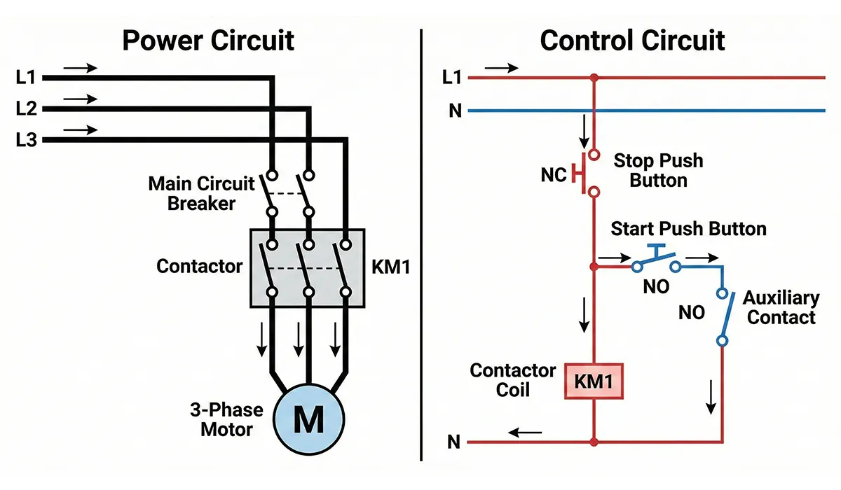
Power Circuits
All connections that transfer electrical energy from the supply network to the load are classified as power circuits. These circuits carry the main current required to operate equipment such as motors, heaters, lighting systems, and other electrical loads. A typical example is a three-phase contactor delivering three-phase current through its main contacts to drive an industrial motor. Power circuits must be sized to handle continuous rated current plus any surge currents during starting or switching events.
Power circuit design considers conductor ampacity, short-circuit withstand capability, voltage drop limitations, and thermal management. The conductors, protective devices, and switching equipment in power circuits must be coordinated to ensure safe, reliable operation under all anticipated conditions including normal load, overload, and fault scenarios.
Control Circuits
The control circuit encompasses the portion of the installation that manages contactor switching and load operation without directly conducting the load current. This circuit has no electrical connection with the power circuit and operates through the contactor coil to energize or de-energize the main contacts, thereby switching the load ON or OFF. Control circuits typically operate at lower voltages (24V DC, 110V AC, 230V AC) and carry minimal current compared to power circuits.
Control circuit design enables complex logic, interlocking, sequencing, and automation functions using combinations of push buttons, selector switches, auxiliary contacts, timers, and relays. Modern control circuits increasingly incorporate programmable logic controllers (PLCs) and digital control systems that provide sophisticated control algorithms, remote monitoring, and integration with industrial networks.
Current-Consuming Equipment (Loads)
Current-consuming equipment comprises devices designed to convert electrical energy into other useful forms including mechanical energy (motors, pumps, compressors), thermal energy (heaters, furnaces, ovens), luminous energy (lamps, LED lighting), and electromagnetic effects (solenoids, actuators). Understanding load characteristics—whether resistive, inductive, capacitive, or mixed—is essential for proper circuit protection and component selection.
Load types determine the sizing and characteristics of upstream components. Inductive loads such as motors create starting currents 5-8 times rated current and generate back-EMF during switching. Capacitive loads including power factor correction capacitors and electronic ballasts present inrush currents and harmonics. Resistive loads like incandescent lighting and electric heaters exhibit straightforward current characteristics but generate significant heat.
Types of Switches Used in Electrical Panels
Switches constitute critical electrical panel components used to achieve one or more of the following purposes: circuit control, overcurrent and short-circuit protection, routine ON/OFF switching, and electrical isolation of different sections. The selection of appropriate switch types directly impacts system safety, reliability, and compliance with electrical codes.
Non-Load Break Switches (Disconnectors)
Non-load break switches, commonly called disconnectors or isolators, are designed exclusively to open and close circuits under no-load conditions or when connected equipment is de-energized. These switches provide visible isolation points for maintenance safety but must never be operated under load conditions. Their primary advantage is the visible contact gap that provides positive confirmation of circuit disconnection, essential for personnel safety during maintenance work.
Typical applications include fuse switches and blade disconnectors used for visual isolation in both low-voltage and medium-voltage installations. Fuse switches combine disconnection with overcurrent protection through replaceable fuse elements. Blade disconnectors in medium-voltage panels provide visible air gaps for incoming and outgoing lines, while fused blade disconnectors protect transformers and other equipment.
For a comprehensive understanding of Non-Load Break Switches, we highly recommend reviewing this article.
Load Break Switches
Load break switches are engineered to safely interrupt circuits carrying rated voltage and current, and must withstand fault currents for specified durations without damage. These switches incorporate arc extinction chambers, rapid contact separation mechanisms, and robust construction to handle the electrical and thermal stresses of load breaking. Examples include automatic circuit breakers (MCCBs), air circuit breakers (ACBs), and vacuum circuit breakers (VCBs).
Key load switch variants include blade fuse switches combining disconnection with fuse protection, and rotary selector switches used for less critical loads, phase selection, and control panel functions. Rotary selector switches offer flexibility through multiple pole configurations, making them valuable for complex control schemes requiring manual selection between operational modes or sources.
Automatic Circuit Breakers (Molded Case Circuit Breakers)
Automatic circuit breakers represent one of the most important electrical panel components, providing both manual switching and automatic protection against overload and short-circuit conditions. Through adjustable trip relays and settings, these devices deliver tailored local circuit protection and remain immediately operable after trip events without component replacement, unlike fuses.
| Circuit Breaker Characteristics | SPECIFICATION |
|---|---|
| Rated operational voltage (Ue) | Voltage Rating |
| Rated current (In): 15A to 6300A typical range | Current Rating |
| Short-circuit breaking capacity (Icu): up to 150kA | Breaking Capacity |
| Thermal trip (bimetal) for overload protection | Overload Protection |
| Magnetic trip (solenoid) for short-circuit protection | Short-Circuit Protection |
| Electronic trip units with advanced protection functions | Electronic Trip |
| Adjustable thermal and magnetic trip settings | Trip Adjustment |
| IEC 60947-2 or UL 489 compliance | Standards |
| IP20 to IP65 depending on application | Enclosure Rating |
| Modular or fixed installation configurations | Mounting Type |
Thermal and Magnetic Release Mechanisms
Circuit breakers with thermal and magnetic releases provide two-tier protection. The bimetallic thermal element responds to sustained overload conditions by heating and bending until it triggers the trip mechanism—this inverse time characteristic allows brief overloads (motor starting) while protecting against sustained overcurrent. The magnetic coil provides instantaneous protection against short-circuit currents, operating within milliseconds when current exceeds the magnetic trip threshold.
Critical Adjustment Principle: The thermal trip (bimetal) setting of a circuit breaker must be based on the actual operating current of the protected circuit, not the breaker’s rated current, to ensure accurate protection. The upper limit of this setting should not exceed the breaker’s rated current. For example, a 250A-rated breaker protecting a circuit with 230A operating current should have its thermal trip set to 230A for optimal protection.
Construction Requirements for Automatic Circuit Breakers
The breaker enclosure must be manufactured from phenolic resin, high-purity polyester, or equivalent materials with excellent thermal stability and arc resistance. The operating mechanism requires high switching speed and must open and close contacts instantaneously, independent of handle operation speed—this “trip-free” characteristic ensures the breaker cannot be held closed against a fault condition. The mechanism must disconnect all poles simultaneously to prevent single-phasing of three-phase loads.
Terminals on both supply and load sides must accommodate cable lugs or busbar connections with adequate contact area and clamping force. The breaker design must perform correctly regardless of mounting orientation (horizontal or vertical). After a trip event, the handle must indicate a fault condition by positioning between ON and OFF indicators, and the breaker cannot be reset to ON without first moving the handle fully to the OFF position.
Nameplate Information Requirements
Every circuit breaker must display the following information on a durable nameplate with permanent markings: applicable standard (IEC 60947-2, UL 489, etc.), rated voltage and number of phases, rated current, breaking capacity values for specified voltages, manufacturer name or trademark, rated frequency, country of manufacture, and degree of protection (IP rating). The rated current must be clearly visible without removing the breaker from its installed position.
Miniature Circuit Breakers (MCBs)
Miniature circuit breakers differ from molded-case circuit breakers in their lower breaking capacity (typically 6kA to 25kA), smaller current ratings (up to 125A), more compact dimensions, and lower cost per pole. MCBs installed in panels must be of the thermal-magnetic type with enclosures providing durable thermal and mechanical strength to withstand rated current conditions continuously.
MCBs follow characteristic curves (B, C, D, K, Z) that define magnetic trip thresholds relative to rated current. Type B trips at 3-5× rated current (suitable for residential and lighting circuits), Type C at 5-10× (general industrial use and small motors), and Type D at 10-20× (protecting circuits with high inrush currents such as transformers and large motors). Selection of the appropriate curve type prevents nuisance tripping while ensuring adequate fault protection.
Important Limitation: Miniature circuit breakers must not be used as ordinary switches for routine circuit switching operations. Their design prioritizes protection over frequent switching duty, and repeated manual switching accelerates contact wear and reduces short-circuit breaking capacity. Use contactors or load switches for routine ON/OFF control, reserving MCBs for protection and emergency disconnection.
Switch Selection Criteria for Electrical Panels
Switches serve as devices for controlling electrical current and must handle all anticipated currents without thermal effects or dynamic forces damaging the device. When open, the switch must reliably withstand electrical potential difference between contacts. All switch components require adequate insulation strength for applied voltages under expected operating conditions. Selection depends on circuit requirements and must conform to applicable standards.
Rated Current Selection by Load Type
The switch rated current must equal or exceed specified values based on load characteristics, unless the switch manufacturing standard indicates otherwise:
- Inductive (motor) loads and similar: 1.25 times maximum load current to accommodate starting currents and power factor considerations
- Resistive loads (incandescent lamps, electric heaters): Equal to maximum load current, as these loads have unity power factor and no inrush
- Capacitive loads and power factor correction capacitors: 2 times maximum load current due to inrush current and harmonic content
- Gas discharge lamps (fluorescent, HID, LED drivers): 2 times maximum load current accounting for ballast characteristics and power factor
Lighting switches for single-phase circuits must operate at minimum 250V and 10A ratings. If a switch is not designed to interrupt full inductive load, its current rating must be selected as twice the intended steady-state load current. The switch degree of protection (IP rating) must match or exceed the panel degree of protection without reducing overall enclosure integrity.
Fuse Selection and Application
Fuse selection depends on the protection objective (overload vs. short-circuit), load characteristics (fast-acting vs. time-delay), and coordination with other protective devices using time-current characteristic curves. When multiple fuses connect in series, upstream fuses should be rated at least 1.6 times the downstream fuse rating to achieve selective coordination and prevent upstream fuse operation during downstream faults.
| Fuse Selection Parameters | CRITERIA |
|---|---|
| Rated voltage must meet or exceed circuit voltage | Voltage Rating |
| Rated current based on adjusted permissible current | Current Rating |
| Breaking capacity (kA) must exceed maximum fault current | Interrupting Rating |
| gG (general purpose), aM (motor), gR (semiconductor) | Operating Class |
| Fast-acting for electronics, time-delay for motors | Time Characteristic |
| IEC 60269 or UL 248 compliance | Standards |
| Blade, cartridge, or cylindrical physical format | Physical Type |
| Must coordinate with upstream and downstream devices | Selectivity |
Class gG fuses (general purpose) maintain circuit continuity from below melting current up to their rated interrupting capacity. Class aM fuses (motor protection) provide protection against short circuits while allowing motor starting currents to pass. Semiconductor protection fuses (gR) offer extremely fast operation to protect sensitive power electronics. Fuses must be easily installable within panels or fuse switches without requiring special tools.
Contactors in Electrical Panels
Contactors function as electrically operated switches for controlling circuits and loads. They enable remote control, automatic operation, and integration into complex control schemes impossible with manual switches. General contactor specifications include rated voltage, rated current (or current code), rated frequency, number of poles, rated power, insulation test voltage, power-frequency withstand voltage, and configuration of auxiliary contacts (normally open and normally closed).
Contactor Application Categories
The utilization category defines a contactor’s suitability for specific load types and duty cycles:
- AC-1: Non-inductive or slightly inductive loads, resistive furnaces (light duty, minimal arcing)
- AC-2: Starting and stopping slip-ring motors (moderate duty, inductive loads, low switching frequency)
- AC-3: Starting and stopping squirrel-cage motors, frequent switching (heavy duty, high inrush, most common industrial category)
- AC-4: Starting, plugging, and jogging of squirrel-cage motors (very heavy duty, extreme electrical stress from repeated inrush)
AC-3 contactors are most common in industrial applications, suitable for inductive and capacitive loads with high switching frequencies. AC-4 contactors withstand more severe duty cycles including motor jogging, plugging, and frequent reversing operations. Load type (lighting, motor, capacitive) and environmental working conditions must be considered during selection. Proper coordination with thermal overload relays and their precise adjustment based on characteristic curves creates an effective protective system.
| Low-Voltage Contactor Specifications | PARAMETER |
|---|---|
| 24V DC to 1000V AC depending on control voltage | Coil Voltage |
| 50/60 Hz for AC coils, DC coils frequency-independent | Rated Frequency |
| 1-pole to 4-pole configurations, 3-pole most common | Number of Poles |
| Air break (standard) or vacuum (high-performance) | Breaking Medium |
| AC-1, AC-2, AC-3, AC-4 per IEC 60947-4-1 | Utilization Category |
| 2.5 kV for control circuits, higher for power circuits | Insulation Test |
| Configurable blocks: 0-8 NO and 0-8 NC typical | Auxiliary Contacts |
| Mechanical: 10-20 million ops, Electrical: 1-2 million | Endurance |
Contactor Construction and Installation
Contactors and their associated conductors must continuously withstand rated load current without damage to the device or adjacent components. Temperature rise during operation must not exceed values specified in relevant standards. Contactors must operate vibration-free with stable contact pressure across their rated voltage range. Auxiliary contacts support command and control functions beyond the main power contacts.
Main power contacts must be replaceable to extend contactor service life. Pole spacing must be uniform to ensure balanced electrical performance. Operating springs must use corrosion-resistant stainless steel or durable coated metals. Contactors should be enclosed in dust-protected housings with all fasteners properly tightened. Nameplates must permanently display rated voltage and current, utilization category, rated frequency, and manufacturer identification.
Measuring Devices and Indicators
Measuring devices and indicators analyze electrical parameters including voltage, current, power, energy, frequency, and power factor. These instruments enable system monitoring, fault detection, energy management, and compliance verification. Panel-mounted analog meters traditionally dominated, but digital multifunction meters now offer superior accuracy, multiple parameter display, data logging, and communication capabilities.
Analog Meters
Analog panel meters must resist moisture and dust ingress, mounting approximately flush with the 2mm-thick mounting surface. Meters require zero-adjustment screws for calibration and must achieve ±1% accuracy at rated values. Ammeters scale according to current transformer (CT) primary current, displaying actual line current. Voltmeter ranges typically span 1V to 500V for various applications.
Voltmeter selector switches enable single meter monitoring of multiple phases using seven-position rotary construction with maintained contacts and no return spring. Switches require clear phase marking (Phase A, Phase B, Phase C, A-B, B-C, C-A, and OFF positions) and suit installation on 2mm panel thickness. The selector arrangement allows phase-to-phase and phase-to-neutral voltage measurement using one instrument.
Power Meters and Energy Analyzers
Modern power meters measure and calculate active power, reactive power, apparent power, power factor, energy consumption, current, voltage, harmonics, and power quality parameters. These multifunction devices replace multiple analog instruments while providing enhanced functionality including data logging, alarm outputs, and communication protocols (Modbus RTU, Modbus TCP, Profibus, EtherNet/IP).
Power meters install in main distribution panels for facility energy monitoring, submetering, and demand management. In AC systems, analyzing parameters such as voltage sags and swells, current unbalance, harmonic distortion, transients, and other power quality factors proves essential for equipment protection, process stability, and energy efficiency. Advanced power meters with waveform capture capabilities diagnose complex power quality problems.
Signal Lamps and Indication
Signal lamps provide visual indication of equipment status including ON condition, OFF condition, fault conditions, alarm states, and operational modes. Panel-type indicator lamps must be low consumption (LED preferred) and suitable for panel mounting in prepared cutouts. Colored caps must withstand lamp heat without deformation or discoloration—LED indicators eliminate this concern while reducing energy consumption by 90% compared to incandescent lamps.
Common indication schemes include green for normal running, red for fault or alarm, amber/yellow for warning or reduced capacity, white for auxiliary functions, and blue for special conditions per local practice. Flashing indications typically signal abnormal conditions requiring attention. Modern indicators incorporate high-brightness LEDs visible in bright ambient light with wide viewing angles.
Voltage and Current Measuring Transformers
In medium-voltage networks (above 1kV) and high-current low-voltage applications, direct connection of measuring devices and protective relays to the power system becomes technically impractical and economically unfavorable. Voltage transformers (VTs or PTs) and current transformers (CTs) reduce these quantities to standardized values (typically 110V for voltage, 5A or 1A for current) suitable for instrumentation.
Main Functions of Measuring Transformers
- Value transformation: Converting current or voltage from high system values to standardized measurement values suitable for instruments and relays
- Electrical isolation: Providing galvanic separation between high-voltage power circuits and low-voltage measuring/control circuits for safety
- Standardization: Enabling use of standardized protection and metering equipment regardless of primary system voltage or current, reducing variety and inventory while improving reliability
Current Transformers (CTs)
Current transformers connect in series with the circuit being measured, with primary current determined by load rather than CT characteristics. The CT secondary circuit must never be opened while the primary carries current—this creates dangerously high voltages and can damage the transformer. CTs serve two primary purposes: metering (high accuracy at rated current, may saturate during faults) and protection (maintains accuracy during overcurrent and fault conditions for relay operation).
| Current Transformer Specifications | PARAMETER |
|---|---|
| Matches circuit current: 5A to 10,000A+ primary | Primary Current |
| Standardized: 5A or 1A (1A preferred for long runs) | Secondary Current |
| Metering: 0.2, 0.5, 1.0 | Protection: 5P, 10P | Accuracy Class |
| 15, 30, 60 VA typical for metering; higher for protection | Rated Burden |
| Accuracy Limit Factor (5, 10, 15, 20) for protection CTs | ALF |
| Ring/toroidal, bar primary, or wound primary | Construction Type |
| IEC 61869-2 (formerly IEC 60044-1) | Standards |
Protective CTs typically measure large currents and connect to protective relays for short-circuit detection and overcurrent protection. They must maintain accuracy at high multiples of rated current (accuracy limit factor) to provide reliable relay operation during fault conditions. Metering CTs prioritize accuracy near rated current for revenue metering and energy management but may saturate during large fault currents.
Core-Balance Current Transformers (CBCT)
Core-balance CTs feature ring-shaped construction encircling all phase conductors and the neutral. Under balanced conditions with no earth leakage, the vector sum of currents passing through the ring equals zero, producing no secondary current. When earth leakage occurs, current imbalance generates secondary current proportional to the leakage magnitude. This secondary current operates earth fault relays or residual current devices (RCDs) to disconnect the circuit and prevent electric shock or fire hazards.
CBCTs typically install at the origin of final circuits or at main distribution points to provide earth leakage protection for entire installations or specific zones. Sensitivity ranges from 30mA for personnel protection to several amperes for equipment and fire protection. The CBCT must encircle all current-carrying conductors including neutral but must not encircle protective earth conductors.
Earth Fault Relays (Leakage Current Relays)
Earth fault relays, used in conjunction with CBCTs, detect earth leakage currents and issue trip commands to disconnect circuits. These relays incorporate adjustable current thresholds, time delays for selectivity, and alarm/trip outputs. Applications include protecting personnel from indirect contact in TN and TT earthing systems, detecting insulation deterioration before catastrophic failure, and fire prevention by interrupting earth leakage paths that could ignite combustible materials.
Voltage Transformers (VTs/PTs)
Voltage transformers connect between phase conductors and earth (or between phases) in parallel with the system. They step down high voltage to standardized secondary values (110V, 115V, or 120V depending on regional practice) for meters and relays. Inductive voltage transformers (VTs or PTs) use magnetic coupling similar to power transformers but with very low power ratings (typically 25-500 VA).
Capacitive voltage transformers (CVTs) employ capacitive voltage dividers and are more economical for transmission voltages above 100kV. CVTs additionally support power line carrier (PLC) communication used in transmission systems for protection signaling and remote communication. VT secondary circuits typically include two windings: one for metering (higher accuracy) and another for protection (adequate accuracy with larger power capacity).
| Voltage Transformer Specifications | PARAMETER |
|---|---|
| System line-to-earth or line-to-line voltage | Primary Voltage |
| 110V, 115V, or 120V line-to-earth standard | Secondary Voltage |
| 0.2, 0.5, 1.0 (metering) | 3P, 6P (protection) | Accuracy Class |
| 25 to 500 VA depending on connected burden | Rated Burden |
| Single phase or three-phase configurations | Connection Type |
| Electromagnetic (VT/PT) or capacitive (CVT) | Design Type |
| IEC 61869-3 (formerly IEC 60044-2) | Standards |
Conductors Used in Electrical Panels
Panel conductors include wires (flexible or stranded) for equipment interconnection and busbars (rigid solid bars) for main power distribution. While copper dominates due to its excellent conductivity and mechanical properties, aluminum can be specified for special environments where copper would corrode (though this is rare in enclosed panels). Conductor sizing must account for continuous current-carrying capacity, voltage drop, short-circuit forces, and temperature rise.
Wiring Practice
Control wiring inside panels typically uses stranded copper conductors with cross-sections not less than 1.5mm² (14 AWG) for reliability and mechanical strength. Power wiring follows sizing tables based on rated current, installation method, ambient temperature, grouping, and correction factors. Insulation must withstand the working voltage plus test voltages—minimum 1000V test voltage for low-voltage control circuits. Wire colors follow local standards (IEC 60446 or equivalent) for phase identification, neutral, and protective earth.
Wiring must be neat, supported at regular intervals, and routed through wiring ducts or cable trays to maintain organization and allow modifications. For information on industrial wiring selection, proper conductor sizing and installation practices are essential. Ferrules (wire end sleeves) on stranded conductors ensure reliable terminations and prevent strand breakage. All termination points require proper torque application per manufacturer specifications to avoid overheating from loose connections or conductor damage from overtightening.
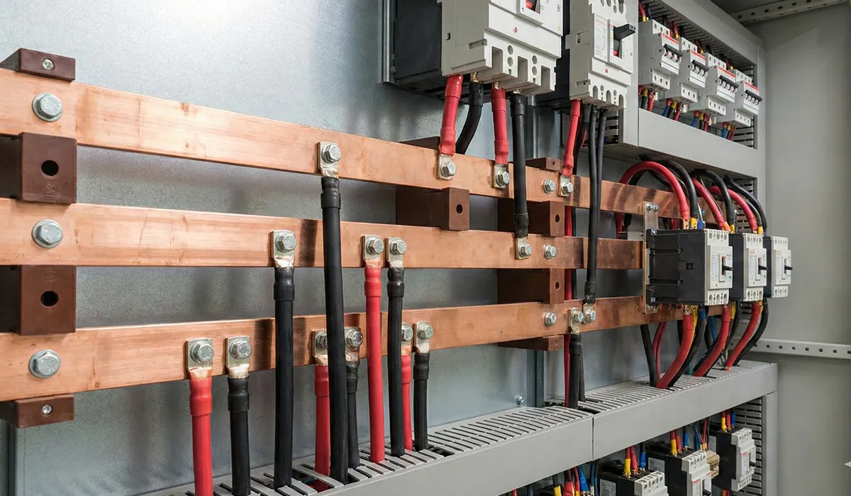
Busbars
Busbars function as the main current-carrying backbone within panels, collecting incoming power and distributing to branch circuits. The simple busbar arrangement connects all equipment to common phase, neutral, and protective earth busbars. In low-voltage panels, busbar spacing depends on the short-circuit level and must not be less than 100mm for installations with high fault currents to prevent flashover and ensure safe separation during maintenance.
Busbar current-carrying capacity depends on cross-sectional area, material (copper vs. aluminum), surface finish (bare vs. tin-plated), mounting orientation (flat vs. edge), ambient temperature, and enclosure ventilation. Typical practice sizes phase busbars at 150% of the main switch rating to provide thermal margin and accommodate future load growth. This oversizing also reduces voltage drop and improves system efficiency.
| Busbar Design Parameters | SPECIFICATION |
|---|---|
| ETP copper (C110) or 6101-T61 aluminum alloy | Material |
| Based on current and temperature rise limits | Cross-Section |
| Bare, tin-plated, or nickel-plated surfaces | Surface Finish |
| Flat (edgewise) or vertical (flatwise) mounting | Orientation |
| Minimum 100mm for high fault current installations | Phase Spacing |
| Must withstand peak short-circuit forces | Mechanical Strength |
| IEC 60439, UL 891, or equivalent standards | Standards |
| Based on supports, span, and fault current | Support Spacing |
Short-Circuit Withstand
Busbars must withstand both thermal and electrodynamic forces during short-circuit events. Thermal withstand ensures the busbar temperature does not exceed limits that would damage insulation or cause annealing of copper. Electrodynamic forces (electromagnetic repulsion between parallel conductors carrying fault current) create bending stresses that can deform or fracture inadequately supported busbars. Support spacing and busbar cross-section must be coordinated with the system short-circuit level to ensure mechanical integrity during faults.
Insulators for Busbar Support
Insulators supporting busbars utilize porcelain or polymer construction selected based on installation location, application, and operating environment. Insulator selection considers busbar dimensions, mounting arrangement, mechanical loads, and electrical stress. The external shape and physical dimensions accommodate busbar width and thickness while providing required creepage distances and clearances.
Critical Inspection Requirements: During insulator installation or periodic inspection, verify no cracking or tracking (carbon path formation from surface discharge) exists on the insulator body. Such damage indicates insulation degradation from overvoltage stress or contamination and requires immediate replacement. When uncertain about insulator condition, perform dielectric testing before returning to service. Forces applied to support insulators must not exceed 50% of their rated mechanical load capacity to provide adequate safety margin.
Insulator Selection Criteria
- Voltage rating: Insulators must be rated for the system operating voltage (low-voltage or medium-voltage applications)
- Mechanical load: Must support busbar weight plus dynamic forces during normal operation and short circuits—load should not exceed 50% of insulator rating
- Electrodynamic capacity: Maximum short-circuit forces must not exceed 75% of insulator mechanical withstand capability
- Creepage distance: Surface path length between conductors must account for contamination level per IEC 60815
- Installation method: Mounting on metalwork and busbar attachment methods must be practical and reliable
- Environmental factors: Consider humidity, altitude, dust, temperature extremes, and temperature cycling severity
Labeling, Coding, and Documentation
All devices, equipment, conductors, terminals, and connection points inside panels must be identified through numbering and standard symbols per IEC 61346 (formerly IEC 61082 and IEC 60848). Proper identification simplifies installation, facilitates efficient troubleshooting, accelerates repairs, and reduces overall costs through improved maintainability. Device labels should use durable materials (engraved laminate or permanent markers) that remain legible throughout the installation lifetime.
Wiring identification uses wire numbers or terminal designations that correspond to electrical drawings. Every wire termination should be labeled at both ends and at intermediate points where wires enter/exit enclosures. Terminal blocks require clear numbering matching schematic designations. Circuit breakers and fuses should be labeled indicating the loads they protect, rated current, and trip curve type (for MCBs).
Panel Nameplate Requirements
Panels and equipment within them require a characteristics nameplate installed in a visible, durable, and legible manner. The panel nameplate must include at minimum: manufacturer name or trademark, panel type designation, current type (AC/DC), rated operating voltage, rated insulation voltage, voltage and rated current of subcircuits, limitations and application conditions, short-circuit withstand rating, panel and personnel degree of protection (IP rating), and panel dimensions.
Standards for Internal Panel Components
Internal panel components must be designed, manufactured, and tested according to applicable international standards to ensure safety, reliability, and interoperability. The following table identifies key standards for common panel components:
| Electrical Panel Component | STANDARD |
|---|---|
| Copper busbars and conductors | IEC 60228, VDE 0201 |
| Aluminum busbars and conductors | IEC 60228, VDE 0202 |
| Low-voltage switchgear assemblies | IEC 61439-1, IEC 61439-2 |
| Low-voltage switches and disconnectors | IEC 60947-3 |
| Circuit breakers for equipment (MCBs) | IEC 60898-1, IEC 60898-2 |
| Molded-case circuit breakers (MCCBs) | IEC 60947-2 |
| Low-voltage contactors (<1000V AC) | IEC 60947-4-1 |
| Motor starters and protection | IEC 60947-4-1 |
| Residual current devices (RCDs) | IEC 61008, IEC 61009 |
| Low-voltage fuses | IEC 60269 series |
| Current transformers (CTs) | IEC 61869-2 |
| Voltage transformers (VTs/PTs) | IEC 61869-3 |
| Panel meters and instruments | IEC 61010-1, IEC 61557 |
| Terminal blocks and connectors | IEC 60947-7-1 |
| Push buttons and pilot devices | IEC 60947-5-1 |
| Programmable controllers (PLCs) | IEC 61131 series |
| Variable frequency drives | IEC 61800-5-1 |
Panel assemblies themselves must conform to IEC 61439 series standards (IEC 61439-1 for general rules, IEC 61439-2 for power switchgear assemblies, IEC 61439-3 for distribution boards). These standards define type tests, routine tests, design verification methods, temperature rise limits, short-circuit withstand, and electrical clearances required for safe, reliable operation.
Installation Considerations
Proper installation of switches, protective devices, and other panel components requires attention to multiple factors beyond simple electrical connections. Installation height should place frequently operated devices between 0.8m and 1.6m above floor level for ergonomic access. Switch mounting depth must account for conductor terminations and ensure adequate clearance behind the device. Minimum distances from auxiliary equipment prevent interference and allow air circulation for thermal management.
Conductor entry and exit locations must align with the panel wiring duct layout and not obstruct other equipment or impede door closure. Service and maintenance access requires sufficient working space per IEC 61439, typically 600mm minimum in front of energized parts rated above 150V to ground. All installation specifications and conditions mentioned in equipment manufacturer documentation must be followed to maintain product certifications and warranty coverage. For proper cable routing, consider using appropriate conduit systems where required.
Medium-Voltage Considerations
Medium-voltage power switches (above 1kV) are selected based on IEC 62271 or equivalent standards and must provide safe operation, maintenance, and repair access. Minimum required safety through suitable interlocks between switches protects personnel and installations—for example, preventing earthing switch closure with the circuit breaker closed, or preventing breaker withdrawal while energized.
Switchgear Performance and Optimization
Modern switchgear systems have evolved significantly beyond traditional circuit breakers to incorporate advanced protection, monitoring, and control capabilities. Optimizing switchgear performance requires careful attention to component selection, proper maintenance schedules, and integration with building management systems.
The coordination between busbars and switchgear creates an electrical harmony that ensures reliable power distribution throughout facilities. Understanding how these systems work together is essential for electrical engineers and facility managers responsible for maintaining continuous power quality and system reliability.
Conclusion
Electrical panel equipment and components form integrated protection, control, and distribution systems essential for safe, reliable electrical installations. Proper selection of circuit breakers, fuses, contactors, switches, measuring instruments, current and voltage transformers, conductors, busbars, and insulators according to IEC standards ensures installations meet safety requirements and perform as designed.
Accurate labeling, documentation, and adherence to installation specifications improve troubleshooting efficiency and reduce lifecycle costs. Engineering discipline in component selection, precise adjustment of protective device settings, and quality installation practices prevent equipment damage, minimize fire risk, and protect personnel from electrical hazards. For specific applications like selecting appropriate breakers, consulting manufacturer specifications and industry standards remains essential.
Frequently Asked Questions
What is an electrical panel and why is it enclosed?
An electrical panel is a protected enclosure housing electrical equipment designed to control, distribute, and protect electrical circuits. Panels are enclosed to improve safety by preventing access to live parts, protecting equipment from environmental factors (dust, moisture, contamination), containing arc flash energy during faults, and providing organized, maintainable installations. Modern enclosed panels incorporate interlocks, segregation barriers, and appropriate IP ratings to ensure personnel safety while enabling reliable operation.
What are the main components commonly found in an electrical panel?
Essential panel components include circuit breakers (MCBs and MCCBs) for overcurrent protection, residual current devices (RCDs) for earth leakage protection, contactors for remote load switching, thermal overload relays for motor protection, fuses for backup protection, current and voltage transformers for measurement, busbars for power distribution, terminal blocks for connections, push buttons and selector switches for operator interface, PLCs or control relays for automation, measuring instruments (ammeters, voltmeters, power meters), and signal lamps for status indication. Supporting components include wire ducts, cable glands, ventilation fans, and space heaters depending on application requirements.
What is the difference between power circuits and control circuits in a panel?
Power circuits transfer electrical energy from the supply network to loads, carrying the main operating current required by equipment such as motors, heaters, and lighting. These circuits use heavy conductors sized for load current and fault current withstand. Control circuits manage contactor coils and protective relay operation to switch and protect power circuits—they are electrically isolated from power circuits, operate at lower voltages (often 24V DC or 110-230V AC), carry minimal current, and implement logic, interlocking, and sequencing functions. A three-phase motor starter illustrates this: the power circuit connects three phases through contactor main contacts to the motor, while the control circuit energizes the contactor coil through push buttons, timers, and auxiliary contacts.
Why is correct selection of protective devices mandatory?
Protective devices must disconnect circuits when current exceeds conductor and equipment ratings to prevent fire, equipment damage, and safety hazards. Improperly selected devices may fail to clear faults quickly enough, allowing conductors to overheat and insulation to ignite, or may nuisance-trip during normal operation, disrupting processes. Selection requires engineering analysis of maximum load current, starting current for motors, fault current levels, conductor ampacity, and coordination with upstream/downstream devices. Standards such as IEC 60364 and local electrical codes mandate proper protective device selection and prohibit installations without adequate protection.


