

Today, electricity consumption management plays a crucial role in both industrial and residential/commercial buildings. Optimal energy use not only leads to reduced operational costs but also directly impacts the lifespan of electrical equipment. Failure to implement solutions such as capacitor banks can lead to serious issues, including poor power quality, unnecessary currents, and ultimately reduced efficiency and lifespan of equipment. This article explores the importance of using capacitor banks, their role in enhancing electrical systems, and how this simple solution can increase the longevity of electrical equipment.
If you’d rather listen than read, feel free to play the audio file below for the rest of this article.
What is a Capacitor Bank and How Does it Work?
A capacitor bank is a collection of electrical capacitors that stores and releases electrical energy in the form of reactive power, compensating for the reactive power consumed in electrical systems. This compensation improves the power factor, reduces voltage drops, and decreases energy losses in distribution networks.
When inductive loads such as motors and transformers generate reactive power, the capacitor bank compensates for it by producing capacitive power, thus improving the system’s power factor. In practice, capacitors store electrical energy in the appropriate phase and inject it back into the system when needed. This process reduces excess currents, minimizes transmission losses, and enhances the overall efficiency of the electrical system.
To better understand the working principle of a capacitor bank, it is helpful to consider the concept of reactive power in more detail. In AC electrical systems, power flows in two distinct forms: active power (measured in watts), which performs actual work, and reactive power (measured in VAR), which oscillates between the source and inductive or capacitive loads without performing useful work. Inductive loads such as motors, welding machines, and fluorescent lighting ballasts are the primary consumers of reactive power. Without compensation, this reactive demand forces the utility network to supply additional current that does nothing productive yet still heats conductors, stresses insulation, and triggers penalty charges on electricity bills. A capacitor bank addresses this problem directly by generating reactive power locally, thereby reducing the reactive current that must be drawn from the grid.
For a comprehensive understanding of capacitor switchboard design, we highly recommend reviewing this article.
Main Components of a Capacitor Bank
- Electrical Capacitors: The main part of the bank consists of capacitors with capacities suitable to compensate for the required reactive power in the system.
- Switches and Control Components: Mechanical or electronic switches are used to connect or disconnect the capacitors either manually or automatically, ensuring precise adjustment of the compensation capacity.
- Protective and Monitoring Systems: These include fuses, protective relays, and monitoring systems that ensure the safety and correct operation of the system against fluctuations and disturbances.
Beyond these three core elements, a fully equipped automatic capacitor bank panel typically also includes a power factor controller (relay), current transformers (CTs) for real-time measurement, detuning reactors to suppress harmonic resonance, and surge arresters to protect against transient overvoltages. The power factor controller continuously reads the reactive power demand of the installation and switches individual capacitor steps in or out to maintain the target power factor. Detuning reactors — connected in series with each capacitor step — are particularly important in installations with variable-speed drives or other nonlinear loads, because they prevent the capacitors from amplifying harmonic distortion already present in the network.
| Description | Component |
|---|---|
| Store and release reactive energy; available in dry-type or oil-filled versions rated for specific kVAR and voltage | Electrical Capacitors |
| Connect or disconnect capacitor steps manually or automatically based on reactive power demand | Switches and Contactors |
| Fuses, relays, and monitoring devices that protect the bank against overvoltage, overcurrent, and overtemperature | Protective Systems |
| Reads system power factor in real time and sends switching signals to maintain the target compensation level | Power Factor Controller |
| Connected in series with capacitors to prevent harmonic resonance and protect against transient overvoltages | Detuning Reactors |
| Measure load current and feed the signal to the power factor controller for accurate reactive power calculation | Current Transformers (CTs) |
If the information related to capacitor bank components was interesting and informative to you, researching electrical panel components can be very engaging.
Types of Capacitor Banks
Capacitor banks are not a one-size-fits-all solution. Depending on the application, load profile, and installation environment, different types are used in practice. Understanding these types helps engineers and facility managers select the most appropriate configuration for their specific needs.
| Key Characteristics | Type |
|---|---|
| Fixed compensation; no automatic switching; used where reactive power demand is constant and predictable | Fixed Capacitor Bank |
| Automatic step switching via a power factor controller; adapts to changing load conditions; most common in industrial facilities | Automatic Capacitor Bank |
| Uses thyristor switching instead of contactors for very fast, transient-free response; suitable for rapidly varying loads | Thyristor-Switched Bank |
| Installed at medium or high voltage level; used in utility substations and large industrial plants for bulk reactive compensation | High-Voltage Capacitor Bank |
| Includes detuned reactors in series with capacitors; designed for installations with significant harmonic content | Detuned (Harmonic-Filter) Bank |
If the details you gathered about capacitor bank types were interesting and insightful, you may find diving deeper into harmonic filter systems equally captivating.
Advantages of Using a Capacitor Bank
Using a capacitor bank in electrical systems offers numerous benefits, optimizing energy consumption, improving efficiency, and reducing costs. These benefits include:
- Reducing Electricity Costs
Capacitor banks improve the power factor of the system, reducing the consumption of reactive power. As a result, unnecessary currents are minimized, and electricity costs are significantly reduced. Many electricity companies charge additional fees for reactive power consumption, which can be eliminated by installing a capacitor bank. - Extending Equipment Lifespan
Improving power quality and reducing excess currents helps electrical equipment such as motors, transformers, and cables experience less thermal stress. This reduces wear and tear, preventing damage and ultimately extending the life of these equipment. Furthermore, capacitor banks ensure better performance of protective systems by minimizing voltage and current fluctuations. - Improving Power Factor
A capacitor bank directly affects the power factor of the system, improving it from a low value (usually less than 1) to an optimal value. A high power factor means more efficient energy usage and reduced energy losses. Installing a capacitor bank can optimize the power factor, benefiting both the system’s economic and technical performance. - Reducing Energy Losses
Capacitor banks reduce energy losses by compensating for reactive power in the network. Reactive power increases current in the system, which leads to energy losses in transmission lines and equipment. By compensating for reactive power, capacitor banks reduce excessive currents, significantly lowering energy losses.
If the content related to capacitor bank advantages was both interesting and helpful, further study of types of electrical panels could be just as fascinating.
How Does a Capacitor Bank Help Extend the Lifespan of Electrical Equipment?
A capacitor bank helps extend the lifespan of electrical equipment by improving power quality and reducing unnecessary loads in electrical systems. Here’s how a capacitor bank affects the lifespan of electrical equipment:
- Reducing Excess Currents
Capacitor banks compensate for reactive power that would otherwise cause excess currents and heavy loads on equipment. Excess currents raise the temperature of cables, transformers, and motors, leading to wear and reduced equipment lifespan. By installing a capacitor bank, these currents are controlled, and the equipment operates at optimal temperatures. - Reducing Voltage Fluctuations
Voltage fluctuations can quickly damage equipment. Capacitor banks stabilize voltage in the system, reducing fluctuations and ensuring that electrical equipment operates in a more stable and healthier condition. This voltage stability prevents damage to sensitive components of the equipment. - Reducing the Negative Effects of Inductive Loads
Inductive loads (such as motors) generate reactive power, which stresses the electrical system and leads to higher energy consumption and faster equipment wear. Capacitor banks help reduce this stress by compensating for reactive power, improving the performance and longevity of equipment. - Reducing Thermal Losses
Reactive power in the system causes more energy to be lost as heat. These thermal losses can damage equipment and reduce their lifespan. By reducing reactive power, capacitor banks minimize energy losses and reduce thermal losses, ultimately extending the life of the equipment. - Improved Performance of Protective Systems
Capacitor banks reduce excess currents and improve power factor, thus reducing the strain on protective systems (such as fuses and relays). This reduction in strain allows protective systems to operate more effectively, preventing faults that could potentially damage equipment.
Since busbars play a crucial role in the distribution of power within electrical panels, obtaining more information about busbars in electrical systems can be very important and essential.
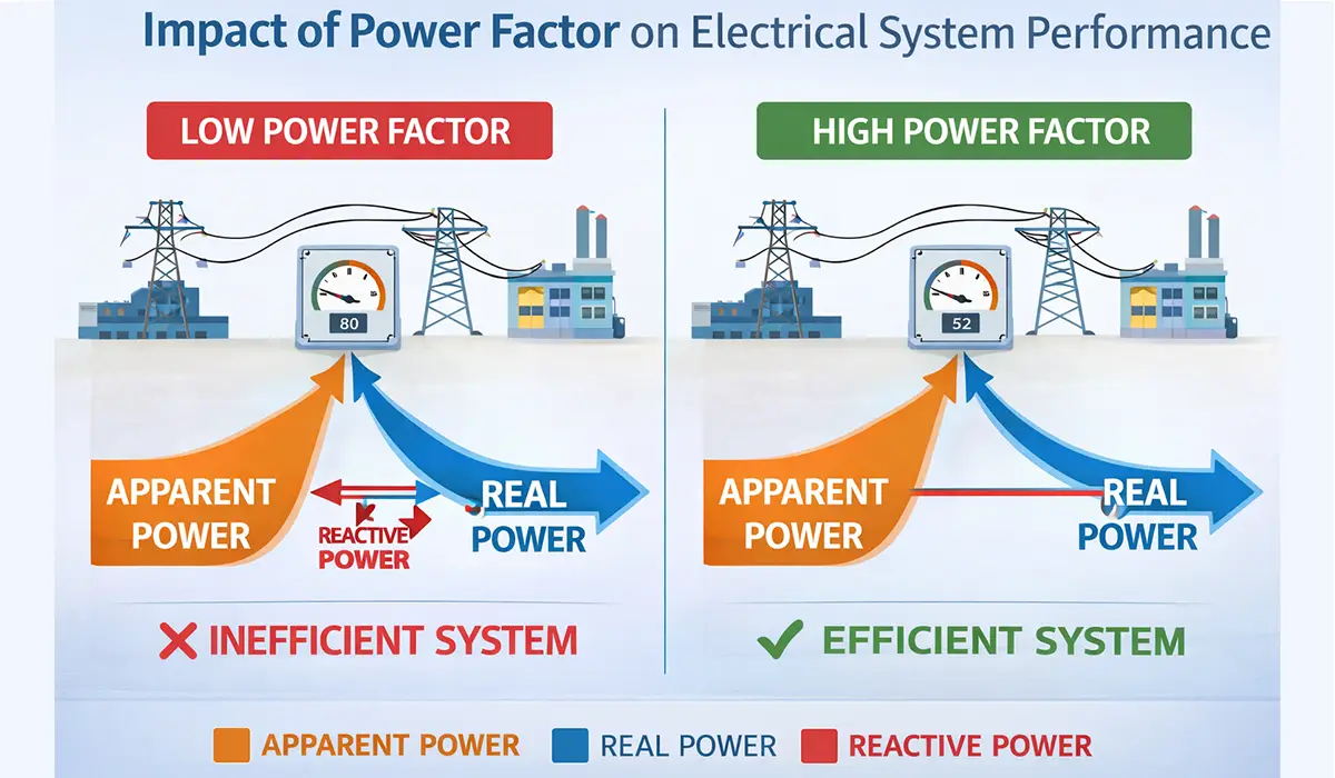
Impact of Power Factor on Electrical System Performance
Power factor is one of the most critical parameters in the design and operation of electrical installations. It is defined as the ratio of active power (kW) to apparent power (kVA) and ranges between 0 and 1. A power factor of 1.0, often referred to as unity power factor, represents the ideal condition in which all current drawn from the supply is used to perform useful work. In contrast, a low power factor — typically anything below 0.90 in industrial settings — indicates that a significant portion of the current in the system is non-productive reactive current.
The consequences of a persistently low power factor extend beyond higher electricity bills. Transformers, switchgear, busbars, cables, and protective devices must all be sized to handle the full apparent current, not just the active component. When reactive current is high, every element in the distribution chain carries more current than it needs to, resulting in accelerated insulation aging, increased risk of thermal tripping, and reduced headroom for additional loads. A well-designed capacitor bank corrects the power factor toward unity, effectively releasing capacity throughout the entire upstream network and deferring or eliminating the need for infrastructure upgrades.
| Effect on System | Power Factor Level |
|---|---|
| Ideal condition; no reactive penalty; all current performs useful work; minimum conductor heating | 1.00 (Unity) |
| Acceptable in most industrial installations; minor reactive current; small penalty charges may apply | 0.95 – 0.99 |
| Borderline; noticeable reactive current; increased losses; correction recommended to avoid penalties | 0.85 – 0.94 |
| Poor power quality; significant energy losses; reactive penalty charges; risk of equipment overheating | 0.70 – 0.84 |
| Very poor; high reactive consumption; severe penalties; immediate capacitor bank installation required | Below 0.70 |
If the information on power factor impact was engaging and informative for you, gathering more knowledge about high voltage vs low voltage could be very exciting.
When Do We Need a Capacitor Bank?
A capacitor bank is required when inductive loads (such as motors, transformers, and similar equipment) are used in electrical systems and the power factor is low. In such situations, the system experiences high reactive power consumption, leading to:
- Increased Energy Losses
Excess currents caused by reactive power lead to voltage drops and increased thermal losses in cables and equipment. - Additional Costs
Many electricity companies impose costs and penalties for high reactive power consumption, which can be eliminated with a capacitor bank installation. - Decreased System Efficiency
Inefficient energy use and increased load on equipment result in reduced lifespan and unstable system performance.
If the insights you gained from this section were intriguing, exploring supercapacitor technology might be of great interest to you as well.
Key Considerations for Sizing and Installing a Capacitor Bank
Correct sizing is the foundation of a successful capacitor bank installation. An undersized bank will leave a portion of the reactive power uncompensated, failing to eliminate penalty charges or fully relieve the network. An oversized bank, on the other hand, can lead to leading power factor conditions, which cause voltage rise, potential resonance problems, and in some cases additional penalty charges from the utility. The goal is to select a bank capacity that brings the power factor as close to the target value as possible under all anticipated load conditions.
The starting point for sizing is an energy audit or power quality measurement campaign carried out over a representative period — typically one to two weeks — using a power analyzer installed at the main incomer of the installation. The data collected shows the reactive power demand at different times of day and under different production conditions, allowing the engineer to determine both the total kVAR of compensation required and the appropriate number and size of switching steps.
Installation location is another important factor. Centralized compensation, where a single bank is connected at the main low-voltage switchboard, is the simplest and most economical approach and is suitable for most industrial and commercial buildings. Group compensation, where smaller banks are installed at the feeder level for clusters of similar loads, offers better network relief within the building. Individual compensation, where a dedicated capacitor is mounted directly at the terminals of each large motor or transformer, provides the highest degree of reactive current reduction within the downstream wiring but requires more hardware and maintenance effort.
| Best Application | Installation Method |
|---|---|
| Most cost-effective; single bank at main LV switchboard; reduces reactive demand at the utility meter | Centralized Compensation |
| Banks installed at sub-distribution level; reduces reactive current in feeder cables; suitable for large facilities with distinct load zones | Group Compensation |
| Capacitor mounted directly at each motor or transformer terminal; eliminates reactive current from all internal wiring; highest efficiency gain | Individual Compensation |
This article serves as a valuable resource for those seeking detailed information on industrial electrical switchboards.
Maintenance and Safety of Capacitor Banks
Like any electrical equipment, capacitor banks require periodic inspection and maintenance to ensure reliable long-term operation. Capacitors age over time due to thermal cycling, voltage stress, and harmonic loading. The most common failure modes include capacitor element breakdown, which can cause the unit to bulge or rupture, and degradation of the internal dielectric, which gradually reduces capacitance and increases power losses within the unit itself.
A routine maintenance program for a capacitor bank should include visual inspection for physical damage or swelling of capacitor cans, thermal imaging to detect hot spots caused by failing elements or loose connections, measurement of capacitance and tan delta to identify units approaching end of life, and verification that the discharge resistors are functioning correctly. Discharge resistors are built into every capacitor unit and are designed to reduce the terminal voltage to a safe level — typically below 75 V — within a specified time after disconnection. This is a critical safety feature because a charged capacitor bank can deliver a lethal shock if touched immediately after switching off.
Contactor wear is another maintenance concern specific to automatically switched banks. Each switching operation subjects the contacts to a brief arc, and over time the contact surfaces erode. Capacitor-duty contactors are specially designed with pre-charge resistors or peak voltage synchronization to minimize the inrush current surge at the moment of switching, but they still have a finite contact life that must be respected. Replacement intervals should follow the manufacturer’s guidelines based on the number of switching operations rather than calendar time alone.
If you enjoyed learning about capacitor bank maintenance, investigating testing electrical switchboards might also offer a similarly engaging and informative experience.
Final Thoughts
Thus, using a capacitor bank is an essential economic and technical solution when reactive power compensation, power factor improvement, and energy loss reduction are needed. This solution contributes significantly to improving energy quality and enhancing the efficiency of electrical systems.
Further exploration of capacitor bank can be found in the following recommended reading.


