




This guide explains how capacitor banks are connected, why capacitor inrush current occurs, which factors set its magnitude and what damage it causes. It then shows how to calculate it with a worked example, how capacitor bank switching works in practice and which mitigation methods suit each application. It closes with the relevant electrical standards.
Prefer listening? You can play the audio version of the rest of this article below.
Understanding Capacitor Banks in Power Systems
A capacitor bank is a group of capacitor units connected in series and parallel to supply reactive power to an electrical network. Inductive loads such as motors and transformers draw lagging reactive power. The capacitor bank supplies leading reactive power locally, which improves power factor and reduces the current carried by transformers and cables. For background on how generation, transmission and distribution fit together, see this overview of the electric power system.
Capacitor Bank Connection: Star (Wye) vs Delta
In low-voltage systems (up to 1 kV), three-phase power factor correction capacitors are almost always delta-connected. Each element sees the full line voltage, so a delta connection delivers three times the kvar of a star connection for the same capacitance.
Medium- and high-voltage banks are usually star (wye)-connected, either grounded or ungrounded. Large banks often use a double-star (split-wye) arrangement, so that a neutral current or voltage unbalance relay can detect failed elements early. The capacitor bank connection matters for inrush calculations: the worked example later in this article uses the equivalent per-phase (star) capacitance.
Capacitor Bank Circuit: Main Components
A typical automatic low-voltage capacitor bank circuit contains:
- Incomer: a main switch-disconnector or MCCB that isolates the whole panel.
- Step protection: HRC fuses or an MCCB for each capacitor step.
- Switching device: a capacitor-duty contactor (or thyristor switch) for each step.
- Reactor (optional): a detuning or current-limiting reactor in series with each step.
- Capacitor units: with built-in discharge resistors.
- PFC controller: measures power factor through a CT on the incomer and switches steps in and out.
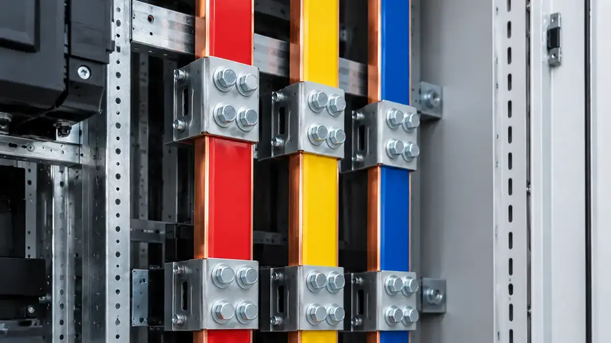
Cables, fuses and busbars in each step circuit are usually sized for at least 1.3–1.5 times the capacitor rated current, to cover harmonics and capacitance tolerance. They must also carry the inrush peaks without excessive mechanical stress, which is why the busbar layout in a capacitor panel deserves the same care as in any busbar-based switchboard.
Types of Capacitor Bank Configurations
Fixed capacitor banks stay permanently connected and supply constant compensation. They are simple and cheap, and suit loads with steady reactive power demand, such as a large motor that runs continuously.
Manually switched capacitor banks let an operator connect or disconnect stages based on measured power factor. They suit loads that change slowly and predictably.
Automatically switched capacitor banks use a PFC controller to switch stages as the load changes. They hold the target power factor (typically above 0.95) without operator action and are the most common choice in industry. Because they switch often, they are also the type most exposed to inrush current problems.
Benefits of Power Factor Correction
Utilities often penalize power factors below 0.90 or 0.95. A 500 kW plant running at 0.75 power factor draws about 667 kVA. Correcting it to 0.95 cuts the demand to about 526 kVA, which lowers demand charges, reduces I²R losses and frees transformer and cable capacity without new infrastructure. These benefits only last if the bank is designed for the switching transients it will see, and inrush current is the most important of them.
Defining Capacitor Bank Inrush Current
Inrush current, also called the energization or switching transient, is the high current surge that flows into a capacitor bank at the moment it is connected to a live system. A discharged capacitor has zero voltage across it, so at the instant of closing it behaves almost like a short circuit. The current is limited only by the inductance and resistance of the circuit until the capacitor charges to system voltage.
Comparison with Rated Current
Rated current is the steady-state RMS current after the transient has died out. For a three-phase bank: I_rated = Q / (√3 × V_LL), where Q is the bank rating in var and V_LL is the line-to-line voltage.
A 50 kVAR bank on a 400 V, 50 Hz system has a rated current of about 72 A. Its peak inrush current can be 720 to 1,440 A, or 10 to 20 times rated current, depending on system inductance and the switching instant.
| Current Comparison Parameters | VALUES |
|---|---|
| Rated current (50 kVAR, 400 V) | 72 A |
| Peak inrush, single bank (10–20×) | 720–1,440 A |
| Peak inrush, back-to-back switching | 50–100× rated |
| Transient duration | A few milliseconds |
| Oscillation frequency | Hundreds of Hz to several kHz |
| Worst-case switching instant | Voltage peak |
Inrush Current Waveform Characteristics
At switch closure the current rises to a sharp peak, then oscillates at the natural frequency of the circuit, f₀ = 1 / (2π√(LC)), where L is the circuit inductance and C the bank capacitance. This oscillation is superimposed on the normal 50 or 60 Hz current. Circuit resistance damps it, and the envelope decays with a time constant of about τ = 2L/R. In low-voltage systems the transient has usually disappeared within one cycle, leaving only the steady-state rated current.
Critical Factors Affecting Inrush Current Magnitude
Several system parameters decide how severe capacitor bank inrush current will be. Knowing them lets engineers predict inrush levels at the design stage and choose mitigation that complies with standards for switchgear and busbar systems.
Capacitance Value
For a given circuit inductance, peak inrush current rises with the square root of capacitance. Doubling a bank from 50 to 100 kVAR increases the peak by about 1.4 times, not 2 times. Because rated current doubles, the inrush multiplier (peak divided by rated current) actually falls for the larger bank. For background on the property itself, see this article on capacitance.
Source Inductance and Short-Circuit Capacity
The inductance between the source and the bank is the main limit on inrush current. The peak is approximately I_peak ≈ V_peak / Z₀, where Z₀ = √(L/C) is the surge impedance of the circuit. A “stiff” system with high short-circuit capacity has low inductance and therefore higher inrush.
For example, a 1,000 kVA, 400 V transformer with 6% impedance contributes about 30 µH per phase. Fifty metres of cable adds roughly 15 µH more, at a typical 0.3 µH per metre. A bank connected directly at the transformer terminals sees noticeably higher inrush than the same bank at the end of a long feeder.
How to Cut Wiring Duct: Tools, Techniques, and Tips for a Clean Result
Knowing how to cut wiring duct properly separates a tidy, code-ready control panel from a messy one. Panel builders cut PVC raceway every day, yet rough edges, cracked walls, and short pieces keep showing up in finished enclosures. This guide walks you through tool selection, technique, and finishing — the same workflow used in professional shops. First, we cover why a clean cut matters. Then we look at duct types, available tools, a step-by-step cutting procedure, common mistakes, corner joints, and safety. By the end, you’ll know exactly how to cut wiring duct cleanly, squarely, and quickly, whether you’re prepping ten metres for a single enclosure or hundreds of metres for a production run.
Switching Instant Relative to Voltage Waveform
The point on the voltage wave at which the contacts close causes the widest variation in inrush current. If an uncharged capacitor is connected at a voltage zero, there is no voltage difference to drive a surge, and the current starts almost at its normal value. If it is connected at the voltage peak, the full peak voltage is applied across the empty capacitor and the inrush is at its maximum.
Example: a 75 kVAR, 400 V bank has a normal peak current of about 150 A. Closed near a voltage zero, its inrush barely exceeds that figure. Closed at the voltage peak with 50 µH of circuit inductance, it can reach about 1,800 A. Ordinary mechanical contactors close at random points on the wave, which is why measured inrush varies so much from one operation to the next.
Back-to-Back Capacitor Bank Switching
When a capacitor step is switched on while other steps on the same bus are already energized, the charged steps discharge into the new one through only the short busbar and cable between them. The source inductance is bypassed, so the inrush is far higher and faster than when a single bank is energized.
The peak can be estimated with I_peak ≈ V_peak × √(C_eq / L_b), where C_eq = C₁C₂ / (C₁ + C₂) and L_b is the inductance between the banks. Two 100 kVAR steps in the same 400 V panel, with about 3 µH between them, give a peak of roughly 5,950 A at almost 3 kHz. That is about 41 times rated current, and lower interconnection inductance pushes it toward 50–100 times. This current stresses both the closing contactor and the already-energized capacitors, and can blow fuses or damage capacitor elements. Automatic multi-step banks always operate in back-to-back mode, which is why their switching devices need special attention.
Residual Voltage on the Capacitor Bank
After disconnection, a capacitor keeps its charge and discharges only slowly through its discharge resistors. If it is reconnected while still charged, the inrush depends on the difference between system voltage and residual voltage at the moment of closing. With 300 V left on the capacitor, reconnecting at +327 V gives only a small surge. Reconnecting at −327 V applies more than 600 V across the circuit and almost doubles the inrush.
IEC 60831-1 therefore requires low-voltage capacitors to discharge to 75 V or less within 3 minutes. IEEE Std 18 requires 50 V within 1 minute for units up to 600 V and within 5 minutes above 600 V. PFC controllers add a matching reconnection delay before a step can be switched in again.
| Factors Affecting Inrush Current | IMPACT |
|---|---|
| Larger capacitance (higher kVAR rating) | Increases peak (∝ √C) |
| Lower source inductance (stiff system) | Increases inrush |
| Switching at voltage peak | Maximum inrush |
| Switching at voltage zero | Minimum inrush |
| Back-to-back switching | Severe increase |
| Residual voltage (opposite polarity) | Up to ~2× inrush |
| Series reactor | Decreases inrush |
| Pre-insertion / damping resistor | Decreases inrush |
Equipment Damage and Operational Problems
Uncontrolled capacitor bank inrush current shortens equipment life and disturbs the power system. The main effects below explain why mitigation is required in line with industrial switchboard standards.
Switch and Contactor Damage
The high rate of current rise at closing causes contact bounce, and each bounce draws a small arc that erodes the contacts. In worse cases the contacts weld together and the step can no longer be switched off. A typical example is a 150 kVAR step switched by an ordinary motor-duty (AC-3) contactor: after a few hundred operations its contacts can weld. Contactors for capacitor switching must be rated for utilization category AC-6b under IEC 60947-4-1, or be dedicated capacitor-duty types.
Fuse and Protection Issues
Fuses in each capacitor step must ride through inrush without blowing, so HRC gG fuses are commonly rated at 1.5–2 times the capacitor rated current. Fast-acting fuses may blow during normal switching. Instantaneous overcurrent elements must be set above the inrush peak, or given a short delay, so that energization does not cause nuisance trips. For the wider principles, see our guide to overcurrent protection.
Capacitor Element Degradation
Every energization stresses the capacitor dielectric. Over thousands of operations this damage builds up and leads to element failure, usually seen as a blown fuse or loss of capacitance. Automatic banks that switch 15–20 times a day can reach more than 20,000 operations in three years. Without reactors or controlled switching, capacitors in such banks can fail long before their expected service life.
Voltage Transients, Flicker and Harmonics
The inrush peak causes a brief voltage dip and ringing on the bus. Variable frequency drives may trip on DC bus overvoltage, PLCs and computers may reset, and discharge lamps may flicker. When a medium-voltage bank is switched, the transient can also be magnified at low-voltage PFC capacitors downstream. The high-frequency content of the inrush can excite resonances between capacitors and system inductance. Limits for these disturbances are set by IEC 61000 electromagnetic compatibility requirements.
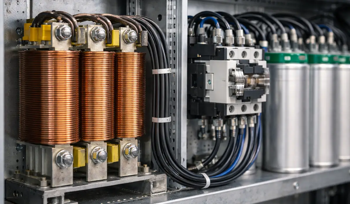
How to Calculate and Measure Capacitor Inrush Current
A quick hand calculation is enough to size switching devices and reactors. Simulation and field measurement then confirm the result. For general background, see this article on inrush current.
Capacitor Inrush Current Formula
For a single bank switched at the voltage peak, and ignoring damping:
I_peak ≈ V_peak × √(C / L)
V_peak is the peak phase-to-neutral voltage, C is the per-phase (star-equivalent) capacitance and L is the total inductance between the source and the bank, including the transformer. For back-to-back switching, use C_eq and the inductance between the banks, as explained above.
Worked Example: 100 kVAR, 400 V, 50 Hz Bank
- Step 1 — Peak phase voltage: V_peak = (400 / √3) × √2 ≈ 327 V.
- Step 2 — Capacitance per phase: C = (Q / 3) / (2πf × V_ph²) = 33,333 / (2π × 50 × 231²) ≈ 1,990 µF.
- Step 3 — Circuit inductance: 1,000 kVA, 6% transformer ≈ 30 µH, plus about 20 µH of cable and busbar, giving L ≈ 50 µH.
- Step 4 — Peak inrush: I_peak = 327 × √(1,990 / 50) ≈ 327 × 6.31 ≈ 2,060 A.
- Step 5 — Rated current: I_rated = 100,000 / (√3 × 400) ≈ 144 A, so the inrush is about 14 times rated current.
- Step 6 — Oscillation frequency: f₀ = 1 / (2π√(50 µH × 1,990 µF)) ≈ 505 Hz.
Effect of a reactor: a 6% reactor on this bank adds about 306 µH (6% of the 1.6 Ω capacitive reactance). Total inductance rises to about 356 µH and the peak falls to roughly 770 A, a reduction of more than 60%.
For more accurate results that include damping and the real switching instant, engineers use simulation tools such as PSCAD, EMTP-RV, MATLAB/Simulink or ETAP. These also show how different reactor sizes compare and whether a design risks harmonic resonance.
Measuring Inrush Current in the Field
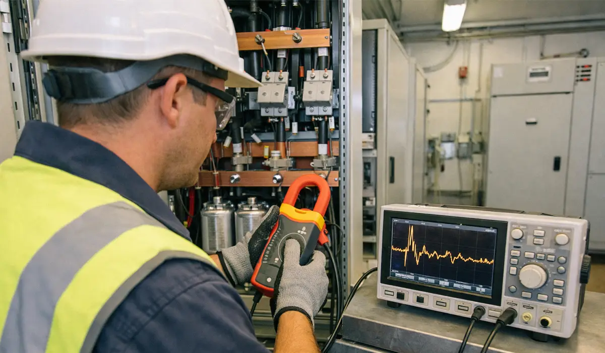
The most accurate method is an oscilloscope or power quality analyser with a high-bandwidth current probe or Rogowski coil. The probe must be rated for the expected peak (often 1–6 kA in low-voltage banks) and have a bandwidth of at least 20 kHz. The capture should be triggered on the rising current and cover at least 20 ms, so that the peak, oscillation frequency, decay and any contact bounce are all recorded. Comparing captures before and after mitigation shows how effective it is.
Peak-hold clamp meters are cheaper and suit routine checks, but they give only a single peak value and may miss very fast peaks. Because these measurements are made on energized equipment, follow the arc-flash PPE requirements of NFPA 70E and IEEE 1584.
Capacitor Bank Switching in Power Systems
Capacitor bank switching covers two different events, and both stress the switching device.
Energization (closing). This produces the inrush current described above. It is most severe in back-to-back switching, which is the normal operating mode of automatic multi-step banks.
De-energization (opening). When a capacitor bank is disconnected, the current is interrupted at a current zero. At that moment the capacitor remains charged at peak voltage. Half a cycle later, the voltage across the open contacts approaches twice the peak system voltage. If the gap breaks down (a restrike), severe overvoltages can follow. This is why capacitive current switching in power systems needs breakers tested for low restrike probability.
The switching device depends on the voltage level:
- Low voltage: capacitor-duty contactors, or thyristor switches for fast-changing loads.
- Medium voltage: vacuum contactors and vacuum circuit breakers rated for capacitive switching.
- High voltage: SF₆ or vacuum breakers, often with controlled switching or pre-insertion resistors.
Good practice for any capacitor bank switching scheme includes the following. Respect the discharge and reconnection delay. Rotate steps so that contactors wear evenly. Set the controller to avoid “hunting”, where the same step is repeatedly switched in and out. Size step protection and busbars for both rated current and inrush peaks.
Proven Solutions for Reducing Capacitor Bank Inrush Current
The right method depends on voltage level, bank size, switching frequency and budget. Whichever is chosen, the installation must still meet pollution degree and overvoltage category requirements.
Capacitor-Duty Contactors with Damping Resistors
This is the standard solution in low-voltage automatic PFC panels. Early-make auxiliary contacts close first and connect the capacitor through small damping resistors. A few milliseconds later the main contacts close and the resistors are taken out of circuit. This damps the first inrush peak, including back-to-back inrush, at low cost and with no continuous losses.
Current-Limiting and Detuning Reactors
A reactor in series with each step adds inductance and lowers both the peak and the rate of rise of inrush current. Reactors are specified as a percentage of the capacitive reactance; 5.67%, 7% and 14% are common detuning values. As the worked example shows, a 6% reactor can cut inrush from about 2,060 A to about 770 A.
Detuning reactors also shift the resonance of the step below the 5th harmonic, protecting capacitors in networks with drives and other non-linear loads. The drawbacks are cost (often 15–30% of the bank cost), space, small continuous losses, and a voltage rise at the capacitor terminals of about 1/(1 − p). A 6% reactor raises the capacitor voltage by about 6.4%, so capacitors with a higher voltage rating (for example 440–480 V on a 400 V system) are needed. The installation must also suit the environment, including its IP and NEMA enclosure ratings.
| Method | Typical Inrush Reduction | Relative Cost | Continuous Losses | Best Application |
|---|---|---|---|---|
| Capacitor-duty contactor (damping resistors) | Damps the first peak | Low | Negligible | Standard LV automatic PFC panels |
| Detuning / current-limiting reactor | 50–75% | Medium (15–30% of bank) | Small | Networks with harmonics, frequent switching |
| Controlled (synchronous) switching | 70–90% | Medium–high | None | MV/HV banks, frequent switching |
| Thyristor-switched capacitors | Near transient-free | High | Thyristor conduction losses | Fast-changing loads (welding, cranes) |
| Pre-insertion resistor / inductor | High | High | None | HV transmission banks |
| Reactor + controlled switching | 90%+ | Highest | Small | Hospitals, data centers, critical sites |
Controlled (Synchronous) Switching
A controller measures the voltage waveform and times the closing command so that the contacts close near the voltage zero of each phase, compensating for the breaker’s mechanical closing time. With consistent closing times (typically within ±1–2 ms on modern vacuum breakers), this cuts inrush to 20–30% of random-switching values, with no added losses or voltage rise. Its limits are higher cost and dependence on accurate voltage measurement and on switching devices with stable closing times. Panels must also meet CE marking requirements for control panels.
Pre-Insertion Resistors and Inductors
In high-voltage breakers, a resistor (or inductor) is inserted in the circuit for a few milliseconds before the main contacts close. The resistor is sized close to the surge impedance of the circuit, which gives the best damping. The method is very effective but adds mechanical complexity and maintenance, so it is mainly used for transmission-level capacitor banks.
Thyristor-Switched Capacitors (TSC)
Thyristor switches connect each step at the instant when the supply voltage equals the capacitor voltage, giving almost transient-free switching. They can operate every few cycles, so they suit loads that change very quickly, such as spot welders and cranes. They require cooling for thyristor losses and are normally combined with detuning reactors.
What about NTC thermistors? NTC thermistors limit inrush in electronic power supplies, but they are not a practical choice for power factor correction banks. Their continuous losses at bank currents and their slow thermal recovery rule them out for automatic switching.
Compliance with International Standards
IEC 60831-1/-2:2014 covers self-healing low-voltage shunt capacitors. Among other requirements, capacitors must withstand switching transient peaks of up to 200 times rated current and discharge to 75 V or less within 3 minutes. IEC 60871-1 covers shunt capacitors above 1 kV. IEC 61921 covers complete low-voltage power factor correction banks.
IEC 60947-4-1 defines utilization category AC-6b for contactors that switch capacitor banks. Standard motor-duty (AC-3) ratings are not sufficient for capacitor switching.
IEC 62271-100:2021 covers high-voltage circuit breakers, including capacitive current switching. Breakers are classified C1 (low probability of restrike) or C2 (very low probability of restrike). The standard also defines a rated back-to-back capacitor bank inrush making current, with a preferred value of 20 kA peak at 4,250 Hz. The equivalent IEEE application guide is IEEE C37.012.
IEEE Std 18 covers ratings and testing of shunt power capacitors, and IEEE Std 1036 is the application guide covering switching transients and back-to-back inrush.
Low-voltage assemblies in Australia and New Zealand follow AS/NZS 61439. Banks installed in explosive atmospheres must also meet ATEX and IECEx requirements.
Typical Field Scenarios
The two scenarios below are composite examples based on common field problems. The figures are representative rather than taken from a single named site.
Scenario 1: Contactor Failures in a Manufacturing Plant
A plant runs three 150 kVAR automatic steps on a 400 V bus, switching 10–15 times a day as welding robots and presses cycle. Its contactors fail every 6 to 9 months. Investigation shows that they are AC-3 motor-duty types with no reactors, and oscilloscope captures show back-to-back inrush peaks of 1,400–2,800 A. Replacing them with capacitor-duty contactors and adding 6% reactors brings the peaks down to 450–600 A. After the retrofit the contactors show minimal wear and the investment pays back in under two years.
Scenario 2: Imaging Equipment Resets in a Hospital
A 300 kVAR automatic bank on a 480 V hospital service causes CT and MRI systems to reset whenever it switches. Power quality monitoring shows voltage transients above ±10% at the imaging equipment, caused by inrush peaks of about 2,100 A. Synchronous switching combined with a 7% reactor reduces the peak to under 400 A and the transient to about ±3%. The equipment resets stop, and the site keeps its power factor improvement while meeting electrical safety standards.
Conclusion and Recommendations: Capacitor Bank Inrush Current
Capacitor bank inrush current cannot be eliminated, but it can be controlled. Its severity depends on bank size, circuit inductance, switching instant, residual voltage and, above all, back-to-back switching, which can push peaks to 50–100 times rated current. Left uncontrolled, it welds contacts, blows fuses, trips sensitive loads and shortens capacitor life.
For most low-voltage automatic banks, capacitor-duty (AC-6b) contactors plus detuning reactors where harmonics are present are the practical answer. Controlled switching and pre-insertion devices are the tools for medium- and high-voltage banks and critical sites. In every case, estimate the inrush with the formula above, check it against the ratings of the switching device and capacitors, and verify it by measurement at commissioning. Proper earthing system design completes a safe and reliable installation.
Frequently Asked Questions about Capacitor Bank Inrush Current



Rate this article
Choose a rating from 1 to 5 stars.
No ratings yet
0 Comments
No comments yet. Be the first to comment.