







If you’d rather listen than read, feel free to play the audio file below for the rest of this article.
Why Enclosure Corners Fail Before Anything Else Does
Corner tearing stops when the compressed metal gets somewhere to go. Shops see clean, crack-free corners straight off the brake, and it comes from one choice: a relief at every two-bend intersection.
The physics is simple. As the punch drives the sheet into a V-die, the outside of the bend stretches and the inside compresses. That compressed material does not vanish. It pushes sideways, towards the bend ends. On a single bend it only bulges. At a corner, two bends force their surplus into the same small area, so the metal bunches, buckles or splits.
Springback adds a second problem. Most sheet metal enclosure design guidelines treat it as an angle error. At a corner it becomes stress concentration, and the locked-in stress pulls both flanges out of square.
Getting these fundamentals right depends on the machine doing the forming as much as the flat pattern feeding it. A closer look at how a metal bending machine handles tonnage and die selection explains why the same design prints differently on different equipment. That relationship between machine capability and corner geometry runs through every rule below.
The 8 Rules for Stronger, Cleaner Enclosure Corners
These sheet metal enclosure design tips all apply at the flat pattern stage, before any tooling is chosen. Fix them in CAD and the press brake gives you repeatable corners.
Budgeting for the equipment that will hold these rules is a separate but related question. Our busbar bending machine price guide breaks down what drives cost across different tooling configurations. It’s worth reading alongside these design rules before finalizing a fabrication budget.
Rule 1—Never Design a Zero-Radius Corner
Cracked outer fibers vanish as soon as the inside radius respects the material. Fabricators see it as crack-free bends on cold-rolled steel and 5052-H32.
The minimum bend radius for sheet metal enclosure panels follows one relationship:
Ri ≥ 1t — cold-rolled steel, galvanized steel, 5052-H32 aluminum
Ri ≥ 2t to 4t — 6061-T6 aluminum, rising with thickness
Below that, the outer fiber stretches past its elongation limit and splits. 6061-T6 is the usual casualty. Several guides quote 1.5t for hard aluminum, but published bend charts put it far higher. Treat 2t as the floor and test a coupon.
Then ignore the CAD default. Software will hold 0.5 mm on every bend, while the shop owns punch tips and V-dies in fixed steps. In air bending, the die opening sets the inside bend radius, not your model. Ask which tooling is stocked first.
Copper busbar work runs into a related radius problem, since the metal behaves differently under the punch than steel or aluminum. Our guide on bending copper busbar covers minimum radii, surface marking and springback control for that material specifically. The same discipline of respecting the material’s limits applies there too.
Rule 2 — Add a Corner Relief at Every Two-Bend Intersection
A relief sized at t + Ri closes the corner cleanly instead of tearing it. Shops measure it as a consistent, weld-ready gap, decided entirely in the flat pattern.
A bend relief sits beside a single bend that ends against a flat area. A corner relief sits where two or three bends meet, as in any tray or sheet metal box design. Same purpose, different location.
So how to design corner relief in sheet metal comes down to three decisions. The relief must extend past both bend lines. Its width should be at least material thickness plus the inside bend radius. Round or square is the third: round spreads stress, square closes tighter.
Size it small when the corner will be welded or sealed: a smaller relief cutout leaves a smaller gap. Most corner relief sheet metal errors start in CAD, where a default 0.1 mm relief tears on the brake.
Not every enclosure fits a standard relief pattern, and busbar assemblies often need geometry outside the usual playbook. See how a custom bending solution was developed for one such non-standard busbar machine application. The same case-by-case thinking applies whenever a stock relief size doesn’t fit the part.
Rule 3—Keep Holes and Cutouts Away From the Bend Line
Ovalled holes stop appearing once the nearest feature sits outside the deformation zone. Inspection sees round holes and in-tolerance hole centres after forming, and the fix is pure layout.
The distance from hole to bend line has two competing rules, and they come from different places. The geometric floor is Ri + t, measured to the edge of the hole. Shop practice is more careful, at 2× to 4× material thickness, and tooling guides push it to 6× t.
Inside that zone the punch actively stretches the material, so a round hole pulls into an oval and a slot skews. If the hole cannot move, move the bend, or punch after forming.
For updated product, service, or technical information, review the source website directly.
Feature placement matters just as much once the panel reaches the switchgear or panel-building stage. Our piece on busbar bending machines in electrical panels looks at how tight tolerances upstream translate into reliable fits downstream. Keeping holes clear of the bend zone is one part of that larger precision chain.
Rule 4—Respect Minimum Flange Height
Flanges stop slipping into the die once they sit on both die shoulders. The proof is a bend angle that repeats within a degree, from one dimension you control in CAD.
The flange height rule sheet metal bending shops apply is four times material thickness, plus the inside bend radius. The reason is contact. The part needs three support points: one under the punch, one on each die shoulder. A short flange loses a shoulder and drops into the V.
When the design truly needs a shorter flange, you have two options. Form it long and trim it back, which adds an operation. Or move to a narrower V-die, which raises tonnage, tightens the radius and costs more. Neither route is free.
You can check this page for more examples, explanations, and related technical resources.
Flange support also depends on which forming equipment is doing the work. Our comparison of bending press vs press brake explains how die shoulder contact and tooling choice differ between the two. That distinction affects how much flange height a given machine actually needs.
Rule 5—Keep Wall Thickness Uniform Across the Part
One formed part comes from one sheet, so uniform wall thickness is a physical limit, not a preference. A 14-gauge base cannot carry a 16-gauge flange without a second part and a weld.
Sheet metal enclosure thickness then follows the duty. Around 1.0 to 1.5 mm suits small electronics housings. Industrial cabinets sit at 1.5 to 2.5 mm. Large floor-standing units start near 2.5 mm. Ribs, hems and flanges add stiffness far more cheaply than the next gauge up.
Over-speccing gauge costs three ways. Material price rises, freight rises with weight, and forming gets harder. Heavier stock needs a wider V-die, more tonnage and a larger inside radius, which changes every corner.
Matching gauge to duty is only half the equation; the machine also needs to be sized for that gauge. Our metal bending machine selection guide walks through tonnage, bed length and other factors to consider before specifying equipment. Getting that match right keeps uniform wall thickness achievable across the whole part.
Rule 6—Choose the Corner Method Before You Draw the Corner
Choosing the corner method first removes an entire redesign loop. You see it as one flat pattern that survives to production, because welded, lapped and cold formed corners each need a different blank.
| Corner Method | Strength | Finish and Rework | Sealing | Best Fit |
|---|---|---|---|---|
| Welded Corner | Highest; a corner-to-corner joint allows full penetration | Heat distortion, grinding, weld porosity risk; ruins galvanized and brushed finishes | Continuous once ground and sealed | One-off parts, heavy plate, unusual angles |
| Lapped Corner with Fasteners | Moderate; depends on fastener pitch | No heat, but a visible seam stays | Leak path along the overlap | Cost-driven indoor enclosures |
| Cold Formed Corner | High; the corner stays one continuous piece | No heat, no grinding, coating survives | Continuous radius the gasket can follow | Repeat production, coated or brushed panels |
Welding gives the strongest joint, and a corner-to-corner overlap allows full penetration. It also drives heat into thin sheet, so panels bow and doors stop closing square. Fixtures and stitch welding reduce that movement, but they add labor. It leaves a bead that someone has to grind. On galvanized or brushed stock, that grinding destroys the finish you already paid for, and porosity in the bead becomes a corrosion start point.
Lapping is cheap and cold, but the overlap is a leak path and the seam shows on a front panel. Decide first, because each method changes the blank you cut.
This source can help you verify the information and continue your independent research.
Corner method is just one decision inside a much longer fabrication sequence. Our overview of the sheet metal fabrication process places welding, lapping and cold forming in that wider context. Seeing where corner treatment sits in the full sequence makes it easier to plan around it.
Rule 7—Design the Corner Around the Gasket
Sealing holds when the gasket compresses to roughly 25–35% of its free thickness all the way round. Published sealing guidance sets that window, and most enclosure leaks trace back to corners outside it.
A corner is where the gasket has to turn, and a sharp corner is where gasket compression drops. The seal lifts, water finds the gap, and the IP65 test fails. Keep the sealing surface continuous, with a generous, consistent corner radius the gasket can follow.
Waterproof sheet metal enclosure design also needs the right rating cited. Use IEC 60529 for IP codes, and NEMA 250 or UL 50E in North America. Those two add corrosion and gasket ageing tests that ingress protection alone does not cover. A relief left open at a corner breaks the seal line.
Visit the linked website to better understand the background, standards, and practical use cases.
Consistent hole and cutout quality around a sealing surface also depends on well-maintained tooling upstream. Our guide to punching machine maintenance and safety covers the upkeep that keeps those features clean and in tolerance. Worn tooling is a common, overlooked cause of gasket-line leaks.
Rule 8—Bend Across the Grain, and Pick the Right Alloy
Bending across the grain holds a tighter inside radius in the same material. One alloy cracks with the grain and forms cleanly across it.
Rolling elongates the crystal structure along the sheet length. A bend line parallel to that grain direction stretches the elongated grains apart, so the outer surface splits. Turn the part on the nest where the flat pattern allows. Mark the grain on the drawing.
Alloy choice does the rest. 5052-H32 forms best and suits most enclosures. 6061-T6 is stronger and machines well, but demands a larger radius. Cold-rolled steel gives stiffness at low cost. 304 stainless resists corrosion and washes down well, but springs back more.
For readers who want more technical depth, this reference page is a useful starting point.
Grain direction and alloy choice matter most on parts with tight, repeatable form factors, like server rack enclosures. Our reference on standard server rack dimensions shows how those constraints shape the flat pattern before a single bend is made. Grain orientation is one more variable to fix at that same design stage.
Quick Reference—Thickness, Radius and Relief at a Glance
One lookup table removes most DFM back-and-forth. Fabricators quote faster from a drawing that already carries a stocked gauge, a workable minimum bend radius and a relief their tooling can cut. Sheet metal enclosure thickness and bend radius travel together, so fix both at the same time. Values below are typical starting points for enclosure work, not universal limits.
| Material | Typical Thickness Range | Minimum Inside Bend Radius | Minimum Relief Width | Note |
|---|---|---|---|---|
| Cold-rolled Steel (CRS) | 0.8–2.5 mm | 0.5t–1t | t + Ri | Most forgiving; typical — confirm with your fabricator |
| Galvanized Steel | 0.8–2.0 mm | 1t–1.5t | t + Ri | Coating cracks at tight radii; typical — confirm with your fabricator |
| 5052-H32 Aluminum | 1.0–3.0 mm | 0.5t–1t | t + Ri | 0.5t only across the grain; typical — confirm with your fabricator |
| 6061-T6 Aluminum | 1.5–3.0 mm | 2t–4t | t + Ri | Rises towards 6t in heavy gauge; consider 6061-T4 instead |
| 304 Stainless | 1.0–2.5 mm | 1t–2t | t + Ri | High springback; expect extra overbend |
Every radius above is a starting value rather than a specification, so confirm it against the punches and dies your fabricator actually stocks. Where the corner will be sealed or cold formed, treat the relief width as a maximum as well, because a wide relief leaves a gap the gasket cannot bridge.
You can explore this trusted source for more complete and updated information.
For a deeper walkthrough of where these radius figures come from, our article on sheet metal bend radius explained covers the underlying formulas in more detail. It’s a useful companion to this quick-reference table when a project needs justification beyond a lookup value.
When Weld-Free Corner Forming Beats Welding
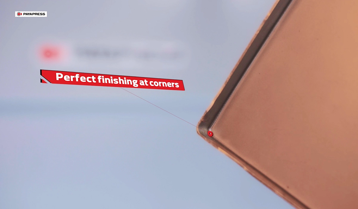
Cold forming removes several secondary operations from a corner. Parts leave the brake ready for paint, with no weld bead, no grinding dust and no heat mark on the panel.
Pre-bend both flanges on a press brake, flare the corner, form it to the target radius, then crop the excess. Compare that with the traditional route of notch, bend, tack, weld, grind and polish. What disappears is a long list: heat distortion, weld porosity, consumables, abrasive dust and rework on coated material.
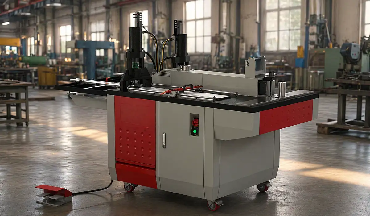
So when does it pay? Any corner forming machine vs welding cost comparison should count corners per shift, not corners per part. Cold forming wins on three triggers: high corner volume, a finish that must survive the process, or a repeatable sealing surface. That last trigger matters most on a custom sheet metal enclosure. PAYAPRESS builds corner forming equipment for that kind of production volume.
Welding still wins for one-off parts, unusual angles and plate beyond the tooling’s forming range. As a planning figure only, shops often model the saving as several minutes per weld-free corner (hypothetical estimate — replace with verified production data before publishing).
Cold forming isn’t limited to corners; the same principle applies more broadly across sheet metal design. Our piece on which sheet metals can be cold formed looks at how alloy and temper decide whether a part is a candidate for this process at all. That broader picture helps when deciding whether cold forming fits a given enclosure design.
Conclusion
Corners decide three things: whether the part is strong, whether it seals, and how good it looks. All three are settled at the flat pattern stage, long before the press brake runs. Get the radius, the relief and the flange height right, and the rest of the panel follows. Then match the corner method to volume — welding for one-offs, cold forming once cabinet sheet metal enclosure design moves into repeat production.
Corner quality is only one stage in producing a finished busbar assembly; cutting accuracy earlier in the process matters just as much. Our overview of busbar cutting machine types covers how to select the right cutting equipment for copper and other conductive materials. Getting both cutting and bending right is what makes a repeatable, production-ready panel.



Rate this article
Choose a rating from 1 to 5 stars.
No ratings yet