


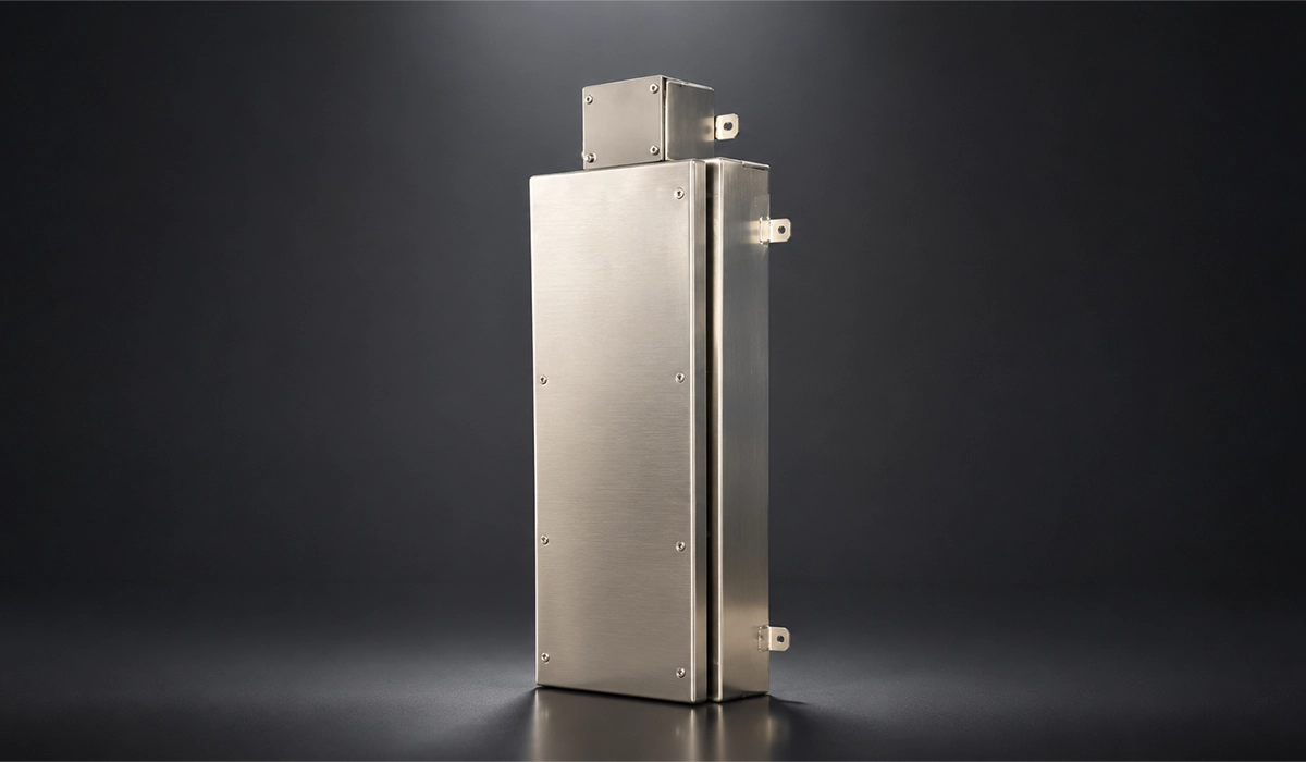





What “Explosion-Proof” Actually Means
Explosion-proof enclosures cover two different protection concepts, and explosion proof enclosure design changes completely depending on which one applies. The table sets them side by side.
| Aspect | Ex d — Flameproof | Ex e — Increased Safety |
|---|---|---|
| Principle | Allows the explosion inside, stops it escaping | Stops any ignition source forming inside |
| Governing Standard | IEC 60079-1 | EN/IEC 60079-7 |
| Typical Body | Cast or machined metal, thick walls | Formed sheet metal, sometimes cast |
| Where the Seal Is | A machined joint with a controlled gap | A compressed gasket between door and body |
| Typical Duty | Switchgear, motors, sparking devices | Terminal boxes, marshalling, cable transit |
You can check this page for more examples, explanations, and related technical resources.
Ex d—Containing the Explosion
A flameproof enclosure Ex d design accepts the explosion and refuses to pass it on. IEC 60079-1 proves that with a non-transmission test: gas ignites inside, nothing outside lights.
The mechanism is a flame path. The joint forces escaping gas through a long, narrow, machined gap that strips its heat away. By the time it reaches the atmosphere, the gas sits below the ignition temperature. IEC 60079-0 carries the general requirements. Note the wording: flameproof is not fireproof. An Ex d body is not designed to survive an external fire.
Ex e—Preventing the Ignition Source
An increased safety Ex e enclosure takes the opposite route. It never lets an ignition source form, so there is nothing to contain.
The difference between Ex d and Ex e enclosures is one of strategy, not quality. EN 60079-7 tightens creepage and clearance, terminal retention, fastener security and ingress protection. It also bans arcing or sparking parts inside. That limits Ex e to passive duties: terminal boxes, marshalling cabinets and cable transit. This concept matters most here, because it is the one usually built from sheet metal.
NEMA 7, Class I Division 1 and Zone Language
Two parallel systems describe the same hazard, and they do not translate one to one. North America classifies by Class and Division. ATEX and IECEx classify by Zone.
Catalogues listing explosion proof nema 7 enclosures use the North American route, where NEMA Type 7 covers Class I, Division 1. Buyers searching explosion proof enclosures nema ratings usually assume a Zone equivalent exists. It does not, at least not automatically. Division 1 maps onto two Zones, 0 and 1, so equipment approval has to be checked rather than inferred.
| Hazard Likelihood | North America (NEC Art. 500) | Zone System (NEC Art. 505, IEC) |
|---|---|---|
| Present Continuously or for Long Periods | Class I, Division 1 | Zone 0 |
| Likely During Normal Operation | Class I, Division 1 | Zone 1 |
| Unlikely, and Only for Short Periods | Class I, Division 2 | Zone 2 |
Why IP66 Is Not Explosion Protection
IP66 tells you about dust and water. It tells you nothing about ignition.
IEC 60529 defines ingress protection and stops there. An enclosure can pass IP66 and still ignite a gas atmosphere, because no part of the IP test examines surface temperature, arcing or flame transmission. When a supplier offers explosion proof electrical enclosures, ask for the certificate number under UL 1203, ATEX or IECEx. The IP figure answers a different question.
Where an Enclosure Is Actually Sealed
“Sealed” means two different things in explosion proof enclosure design, and both meanings arrive at the same place — the corner. One seal is machined, the other compressed.
Flame Paths on Cast Ex d Bodies
On Ex d bodies the seal is machined, not squeezed. Sand cast explosion proof enclosures carry their flame paths on machined flange faces, spigots, cylindrical fits or threads.
The flameproof joint gap requirements IEC 60079-1 sets work as a pair: a minimum joint width against a maximum gap, tabulated by equipment group. Values tighten from IIA through IIB to gas group IIC, because MESG falls as a gas becomes easier to ignite. A flange joint here is a controlled dimension, not a fit-up.
Gasket Lines on Sheet Metal Ex e Bodies
On sheet metal Ex e bodies the seal is a continuous compressed gasket between door and body. Nothing is machined, so everything rests on the sealing surface.
That surface must stay flat, unbroken and undamaged the whole way round, or IP66 will not hold. A silicone gasket covers roughly −60 °C to +200 °C in common grades (typical — confirm against the gasket datasheet). Hinges and latches then decide how evenly it compresses. Explosion proof instrument enclosures fail here more often than people expect, and usually at a door corner.
The Corner — Where Every Seal Line Turns
Every seal line turns at the enclosure corner. That single fact explains most of what follows.
Three problems share the same few centimeters. The seal changes direction, so even compression is hardest to hold. The material was cut and rejoined, so the sealing surface is no longer original. Stress concentrates at the turn, so the geometry moves under load. A leak path anywhere on the enclosure usually begins at this point.
How Corner Quality Affects Sealing
Four separate mechanisms attack the seal, and all four begin at the corner in explosion proof enclosure design. They are geometric, metallurgical and thermal in turn.
Compression Drops Where the Gasket Turns
Explosion proof enclosure gasket compression has a working window, and the corner is where a design falls out of it. Published sealing guidance puts the target near 25–35% of uncompressed thickness (typical — confirm against the gasket datasheet).
A sharp or uneven corner radius makes the gasket stretch outside the turn and bunch inside it. Compression then drops below target across a short arc, and that is enough. Ingress protection follows the worst point on the seal line, not the average, so IP66 fails at one corner.
Weld Porosity Creates Pinhole Leak Paths
Weld porosity is a gas problem that becomes a sealing problem. Trapped gas leaves pores as the weld metal solidifies, and aligned pores form a channel straight through a welded corner.
Visual inspection often misses it. The path appears under pressure test or immersion, sometimes only after grinding opens a subsurface void. Cast bodies carry the same risk in a different form, which is why cast Ex d designs get thick walls and their own pressure testing. On thin sheet, one pore can cross the whole section.
Corrosion Attacks the Weld First
Welding changes the metallurgy locally, and corrosion finds that change. In chloride or marine service, pitting corrosion begins at the heat-affected zone of a corner weld and opens an ingress path.
316L is the usual answer. Molybdenum raises pitting resistance, and low carbon protects the weld zone from chromium carbide precipitation. Anyone weighing a stainless steel vs cast explosion proof enclosure should remember that stainless steel explosion proof enclosures still need the right grade.
Grinding and Heat Distortion Kill Flatness
Heat distortion and grinding attack the same property: flatness. Welding pulls the metal as it cools, and the sealing surface moves out of plane.
Grinding the bead back then removes material unevenly, especially through the turn. The face ends up flat to the eye and out of plane to a straight edge. This is a process problem, not a design problem.
How Corner Quality Affects Safety
In a hazardous area, none of those sealing failures stays a sealing failure for long. Each one has a direct route to an ignition source.
Ingress Becomes an Ignition Source
The chain is short and worth stating plainly. Moisture or dust enters through the corner. It settles on terminals. Tracking, corrosion or a high-resistance joint follows. The joint then heats, and a hot surface or an arc appears.
That arc is exactly the ignition source Ex e exists to prevent. Increased safety carries no containment, so it has no second line of defence. Ingress protection is not a comfort feature on an Ex e box. It is the protection concept itself.
The Corner Carries the Pressure Load
A flameproof enclosure has to survive its own internal explosion. IEC 60079-1 measures the explosion pressure first, calls it the reference pressure, then applies an overpressure test at a multiple of that value.
Corners are stress concentration points, so mechanical strength is decided there. One detail matters for construction. The higher static test factor, which can exempt a design from routine pressure testing, is not available to welded enclosures.
What Certification Actually Tests
Certification checks three things: joint dimensions, non-transmission of an internal ignition, and pressure. UL 1203, ATEX and IECEx all work from a tested sample plus an audited factory.
That second half carries the practical consequence. IECEx issues quality assessment reports so units match the sample, and ATEX adds notified body surveillance. A corner built inconsistently will not repeat what was certified. Certification always belongs to the enclosure manufacturer and its notified body.
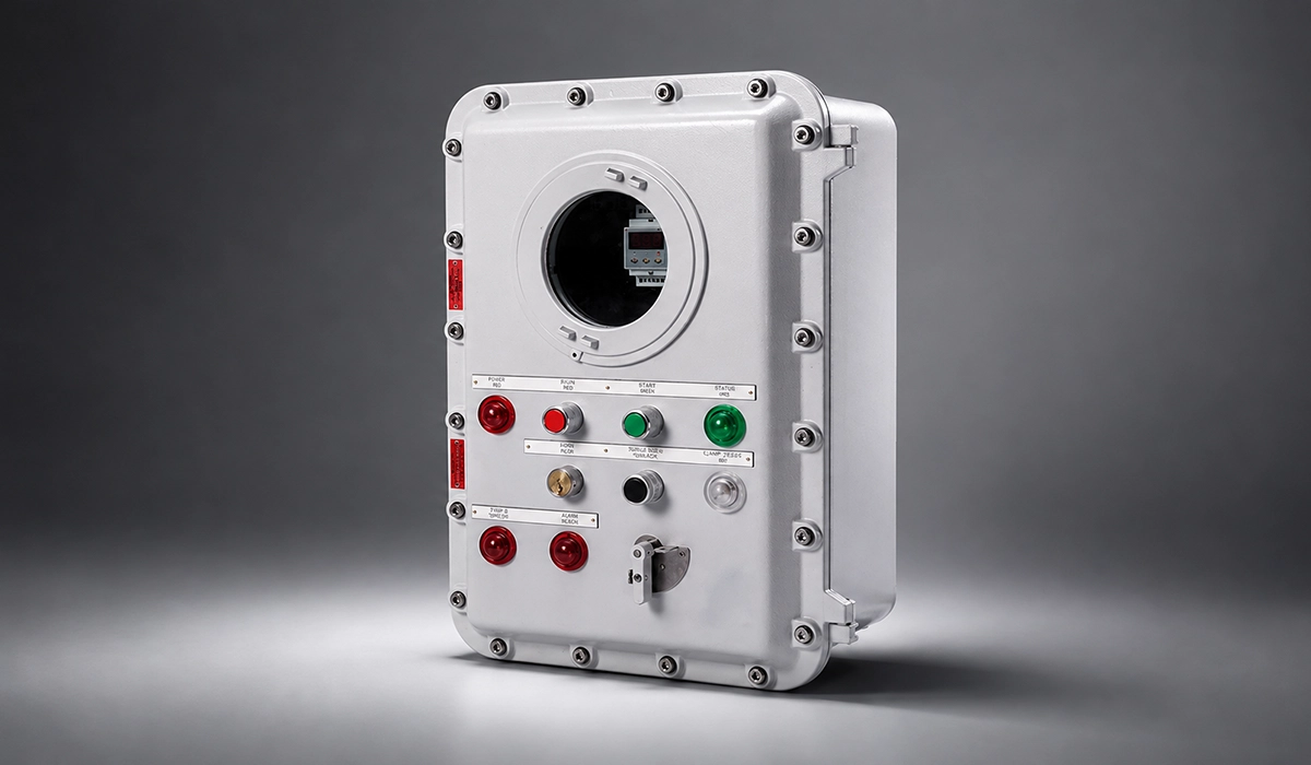
Corner Construction Methods Compared
The enclosure corner method is decided before the flat pattern, not after it, because each route needs a different sheet metal enclosure blank.
| Method | Joint Continuity | Process Cost | Sealing Behaviour | Where It Fits |
|---|---|---|---|---|
| Welded and Ground | Continuous, strong | Heat, porosity risk, grinding, finishing | Good once sound and flat | Certified stainless bodies, low to medium volume |
| Lapped and Fastened | Interrupted by the overlap | Low; no heat | Mechanical leak path, needs sealant | Non-certified, cost-driven indoor boxes |
| Cold Formed | Continuous, one piece of material | No heat, no grinding | Continuous radius the gasket follows | Repeat production, coated or brushed panels |
This source can help you verify the information and continue your independent research.
Welded and Ground Corners
A welded corner is the industry default, and it appears as a spec line on many certified stainless boxes. Custom explosion proof enclosures are usually built this way for sound reasons, because the joint is continuous and strong.
The cost sits downstream, in the operations that follow the arc. Heat input, porosity risk, grinding, finishing and local corrosion sensitivity all arrive together, and every one of them lands on the sealing face.
Visit the linked website to better understand the background, standards, and practical use cases.
Lapped and Fastened Corners
A lapped corner is the cheapest route. Two flanges overlap, and fasteners hold them together.
That overlap is also a mechanical leak path. Fastener pitch decides the clamping force between holes, and the seam stays visible on a front panel. Riveted and bolted joints normally need sealant or a gasket to hold gas or liquid, which rules them out where a certified joint or a continuous gasket line is required.
For readers who want more technical depth, this reference page is a useful starting point.
Cold-Formed, Weld-Free Corners
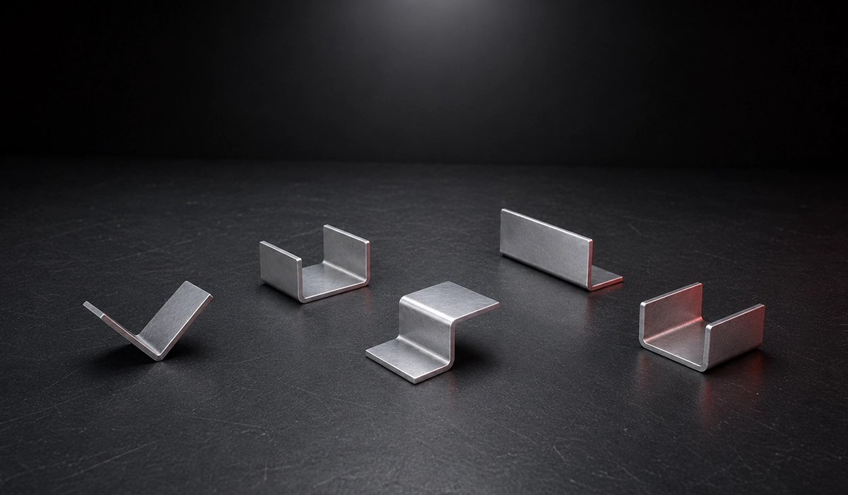
A weld-free corner is formed rather than joined, so no filler metal enters the part. Pre-bend both flanges on a press brake, flare the corner, form it to the target radius, then crop the excess material away.
Heat input, porosity, grinding and weld corrosion sensitivity all leave with the arc. Repeatability is the real gain in sheet metal explosion proof enclosure manufacturing, because certification rests on every unit matching the tested sample.
You can explore this trusted source for more complete and updated information.
Corner Checks Before the Enclosure Ships
Seven checks catch most corner problems before an enclosure ships. None needs a laboratory.
- Corner radius continuous and equal on all four corners.
- Sealing face flat to a straight edge, measured through each turn.
- No visible porosity, undercut or crater at a welded corner.
- Gasket seats evenly around the turn, with no lift or bunching.
- Corrosion protection restored wherever the surface was ground.
- Pressure or immersion test result recorded against the serial number.
- Hazardous-area and gland certificate numbers held on file.
This external page provides additional insights that may help with your evaluation.
Standards Quick Reference
Corner quality touches every standard below, yet none of them mentions corners by name. The requirement always arrives indirectly, through a joint dimension, a pressure value or an ingress rating. Use this table to see which document answers which question, then read your corner requirement into the clause that applies. Editions change, so check the current revision before quoting a clause. None of it replaces the certificate for your specific equipment.
| Standard | What It Covers | When It Applies |
|---|---|---|
| IEC 60079-0 | General requirements for Ex equipment | Always, alongside a protection-specific part |
| IEC 60079-1 | Flameproof “d”: joints, gaps, pressure, non-transmission | Ex d containment designs |
| EN/IEC 60079-7 | Increased safety “e”: creepage, terminals, ingress | Ex e terminal and junction boxes |
| UL 1203 | Explosion-proof and dust-ignition-proof equipment | North American Class I and II, Division 1 |
| IEC 60529 | IP code for dust and water only | Any enclosure, never as explosion protection |
| NEMA 250 | North American enclosure Types, including Type 7 | US and Canadian specifications |
| ATEX Directive 2014/34/EU | Legal conformity route for the EU market | Equipment placed on the EU market |
| IECEx | Voluntary international certification scheme | Global acceptance without repeat testing |
For a clearer comparison, you can review the information provided on this website.
Conclusion Explosion-Proof Enclosures
The chain runs one way. Corner geometry sets gasket compression. Compression sets ingress. Ingress sets the risk of an ignition source at the terminals. The certificate sits on top of all of it. Good explosion proof enclosure design therefore ends where it began, at repeatability: the corner on unit five hundred has to match the corner that was tested.





Rate this article
Choose a rating from 1 to 5 stars.
No ratings yet